18
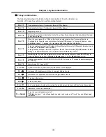
Fn key combinations
The following table shows the function of each combination of Fn with a function key.
Function of Fn keys has nothing to do with Operating System.
Chapter 3. System information
Fn + F1
Customizable hot keys. (Configurable through OSD settings)
Fn + F2
Customizable hot keys. (Configurable through OSD settings)
Fn + F3
Magnifying hot keys.
Fn + F4
Windows Executes the mode defined in the Power Save Mode. (Example: Standby Mode, Maximum
Power Saving Mode)
Fn + F5
When the user presses
Fn
+
F5
keys, the touchpad mode toggles from Touchpad Disable, to
Touchpad Auto
‐
Disable (upon connection of external USB mouse), to Touchpad Enable in order.
(Initialization takes 1 ˜ 2 seconds. It is recommended to use after the initialization.)
Fn + F6
Turns the wireless devices (incl. Wireless LAN and Bluetooth) on and off ( Bluetooth is optional, and
so it may not be installed in some models.)
Through hot key settings in the OSD Tray menu, the user can customize [
Fn
]+[
F6
] features. Default
setting is, for all wireless devices (incl. Wireless LAN and Bluetooth), ON/Off.
Fn + F7
Monitor toggle. If you have an external monitor connected to the computer, press
Fn + F7
keys to
rotate the display mode from
LCD only to Monitor only,
to
LCD + Monitor both
in order.
Fn + F8
Switches between the SRS Off, SRS WOW HD, SRS TruSurround XT modes for each pressing the
Fn
+
F8
keys
Fn + F9
Mute (Sound ON / Sound OFF)
Fn + F10
System Information. System summary information will be displayed.
Fn +
▲
Increases LCD brightness, which can have eight different levels.
Fn +
▼
Decreases LCD brightness, which can have eight different levels.
Fn +
◀
Turns down the volume.
Fn +
▶
Turns up the volume.
Fn + F11
Fan Control feature. Switches the cooling fan mode between Normal and Silent for each pressing.
Fn + F12
Hibernates (When OSD is installed)
Fn + NumLk
Turns the numeric keypad on and off.
“
・
Delete
key types “·” when
Num Lock
is enabled, and works as a "Delete" key when
Num Lock
is disabled.
Summary of Contents for R580 Series U.ARC3BA9
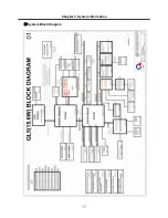
Page 17: ...17 System Block Diagram Chapter 3 System information ...
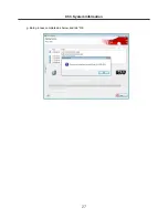
Page 27: ...27 Ch3 System information g Burn process completed as below and tab OK ...
Page 60: ...60 Ch5 Removing and replacing a part 5 Remove the HDD Shield ...
Page 63: ...63 Ch5 Removing and replacing a part 3 Remove the WLAN Module ...
Page 66: ...66 3 Remove the ODD Ch5 Removing and replacing a part 4 Remove the ODD Bezel Bezel ...
Page 69: ...69 69 Ch5 Removing and replacing a part 5 Remove the Keyboard 6 Remove the Retainer ...
Page 71: ...71 71 Ch5 Removing and replacing a part 3 Remove the Display Module ...
Page 74: ...74 Ch5 Removing and replacing a part 3 Remove the Keyboard deck ...
Page 79: ...79 Ch5 Removing and replacing a part 3 Remove the Mainboard Case ...
Page 86: ...86 Ch5 Removing and replacing a part 3 Remove the Hinge Cap ...
Page 98: ...NLCD07 NLCD05 NLCD09 NLCD03 NLCD01 NLCD04 NLCD08 NLCD02 NWEBC01 ...
Page 100: ...NMINI02 NMINI01 NKDECK01 NKDECK02 NRTN01 NKEYBD01 ...
Page 102: ...NMRY01 NMRY01 NMINI04 NTHMO01 NRBS01 NMINI03 NCPU01 NMLB01 ...
Page 105: ...NCVR02 NCVR03 NCVR01 NHDD02 NHDD01 NBATT01 NODD02 NODD01 NBOTM01 NBOTM03 NHDD03 NBOTM02 ...


