47
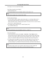
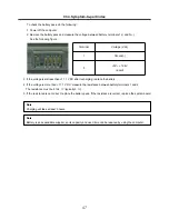
· To check the battery pack, do the following :
1. Power off the computer.
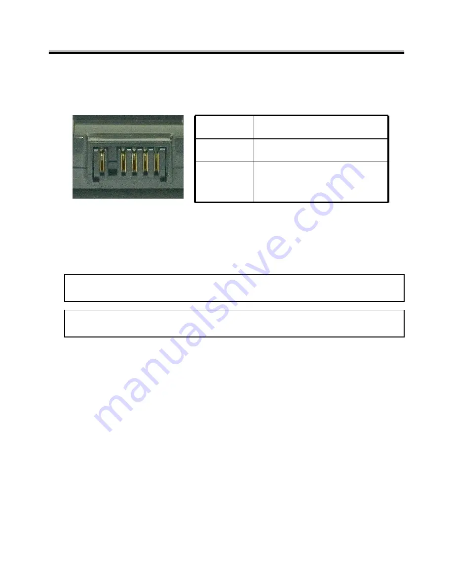
2. Remove the battery pack and measure the voltage between battery terminals 1(-) and 5(+).
See the following figure :
Terminal
Voltage (V dc)
1
Ground(-)
5
+0V ~ +12.6V
(6 cell)
Note
Charging will take at least 3 hours.
3. If the voltage is still less than +11.1 V DC after recharging, replace the battery.
4. If the voltage is more than +11.1 V DC, measure the resistance between battery terminals 1 and 2.
The resistance must be 2 to 4
㏀ (
typically 3
㏀
).
5. If the resistance is not correct, replace the battery pack. If the resistance is correct, replace the system board.
Ch4. Symptom-to-part index
Note
Battery is an expendable supplier, so its capacity and used time can be reduced by using the computer.
5(+)
4
3
2 1(-)
Summary of Contents for R580 Series U.ARC3BA9
Page 17: ...17 System Block Diagram Chapter 3 System information ...
Page 27: ...27 Ch3 System information g Burn process completed as below and tab OK ...
Page 60: ...60 Ch5 Removing and replacing a part 5 Remove the HDD Shield ...
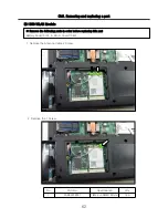
Page 63: ...63 Ch5 Removing and replacing a part 3 Remove the WLAN Module ...
Page 66: ...66 3 Remove the ODD Ch5 Removing and replacing a part 4 Remove the ODD Bezel Bezel ...
Page 69: ...69 69 Ch5 Removing and replacing a part 5 Remove the Keyboard 6 Remove the Retainer ...
Page 71: ...71 71 Ch5 Removing and replacing a part 3 Remove the Display Module ...
Page 74: ...74 Ch5 Removing and replacing a part 3 Remove the Keyboard deck ...
Page 79: ...79 Ch5 Removing and replacing a part 3 Remove the Mainboard Case ...
Page 86: ...86 Ch5 Removing and replacing a part 3 Remove the Hinge Cap ...
Page 98: ...NLCD07 NLCD05 NLCD09 NLCD03 NLCD01 NLCD04 NLCD08 NLCD02 NWEBC01 ...
Page 100: ...NMINI02 NMINI01 NKDECK01 NKDECK02 NRTN01 NKEYBD01 ...
Page 102: ...NMRY01 NMRY01 NMINI04 NTHMO01 NRBS01 NMINI03 NCPU01 NMLB01 ...
Page 105: ...NCVR02 NCVR03 NCVR01 NHDD02 NHDD01 NBATT01 NODD02 NODD01 NBOTM01 NBOTM03 NHDD03 NBOTM02 ...


