49
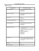
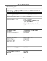
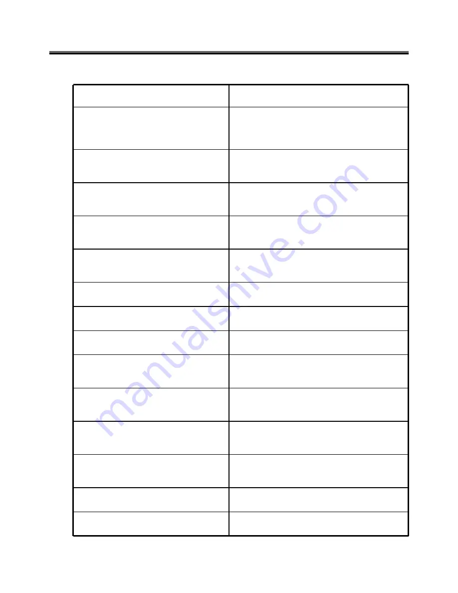
Symptom / Error
FRU or action, in sequence
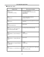
0251
System CMOS checksum bad
– System CMOS checksum is not correct.
– Default configuration used.
Replace the backup battery and run BIOS Setup
Utility
to reset the time and date.
0252
Password checksum bad – The password is
cleared.
Reset the password by running BIOS Setup Utility.
0260
System timer error
1. Replace the backup battery and run BIOS
Setup Utility to reset the time and date.
2. System board.
0271
Check date and time settings – Date and time
error.
Run BIOS Setup Utility to reset the time and date.
0280
Previous boot incomplete
- Default configuration used
1. Load “Setup Default” in BIOS Setup Utility.
2. DIMM.
3. System board.
0281: Memory Size found by POST differed
from EISA CMOS
Load Setup Defaults in BIOS Setup Utility.
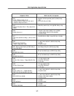
02B0
Diskette drive A error
Set up the diskette type in BIOS Setup Utility.
02B1
Diskette drive B error
Set up the diskette type in BIOS Setup Utility.
02B2
Incorrect drive A type – Floppy diskette drive
error
1. Floppy diskette drive.
2. External FDD cable.
3. I/O card.
02B3
Incorrect Drive B type
1. Floppy diskette drive.
2. External FDD cable.
3. I/O card.
02D0
System cache error – Cache disabled
(RAM cache failed and BIOS disabled)
1. Load “Setup Default” in BIOS Setup Utility.
2. System board.
02F4
EISA CMOS not writable
1. Load “Setup Default” in BIOS Setup Utility.
2. Replace the backup battery.
3. System board.
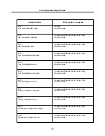
02F5
DMA test failed
1. DIMM
2. System board
02F6
Software NMI failed
1. DIMM
2. System board
Ch4. Symptom-to-part index
Summary of Contents for R580 Series U.ARC3BA9
Page 17: ...17 System Block Diagram Chapter 3 System information ...
Page 27: ...27 Ch3 System information g Burn process completed as below and tab OK ...
Page 60: ...60 Ch5 Removing and replacing a part 5 Remove the HDD Shield ...
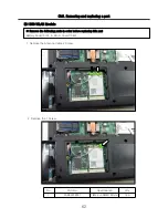
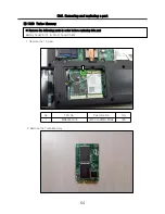
Page 63: ...63 Ch5 Removing and replacing a part 3 Remove the WLAN Module ...
Page 66: ...66 3 Remove the ODD Ch5 Removing and replacing a part 4 Remove the ODD Bezel Bezel ...
Page 69: ...69 69 Ch5 Removing and replacing a part 5 Remove the Keyboard 6 Remove the Retainer ...
Page 71: ...71 71 Ch5 Removing and replacing a part 3 Remove the Display Module ...
Page 74: ...74 Ch5 Removing and replacing a part 3 Remove the Keyboard deck ...
Page 79: ...79 Ch5 Removing and replacing a part 3 Remove the Mainboard Case ...
Page 86: ...86 Ch5 Removing and replacing a part 3 Remove the Hinge Cap ...
Page 98: ...NLCD07 NLCD05 NLCD09 NLCD03 NLCD01 NLCD04 NLCD08 NLCD02 NWEBC01 ...
Page 100: ...NMINI02 NMINI01 NKDECK01 NKDECK02 NRTN01 NKEYBD01 ...
Page 102: ...NMRY01 NMRY01 NMINI04 NTHMO01 NRBS01 NMINI03 NCPU01 NMLB01 ...
Page 105: ...NCVR02 NCVR03 NCVR01 NHDD02 NHDD01 NBATT01 NODD02 NODD01 NBOTM01 NBOTM03 NHDD03 NBOTM02 ...

