5
1-3. Safety information
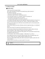
General safety
Follow these rules to ensure general safety
· Observe good housekeeping in the area of the machines during and after maintenance.
· When lifting any heavy object
1. Ensure you can stand safely without slipping.
2. Distribute the weight of the object equally between your feet.
3. Use a slow lifting force. Never move suddenly or twist when you attempt to lift.
4. Lift by standing or by pushing up with your leg muscles
(This action removes the strain from the muscles in your back.)
· Do not attempt to lift any object weights more then 16kg(35lb) or object that you think are too heavy for you.
· Do not perform any action that causes hazards to the customer, or that makes the equipment unsafe.
· Before you start the machine, ensure that other service representatives and the customer’s personnel are
not in a hazardous position.
· Place removed covers and other parts in a safe place, away from all personnel, while you are servicing the
machine.
· Keep your tool box away from walk areas so that other people will not trip over it.
· Do not wear loose clothing that can be trapped in the moving parts of a machine. Make sure that your
sleeves are fastened or rolled up above your elbows. If your hair is long, fasten it.
· Insert the ends of your necktie or scarf inside clothing or fasten it with a nonconductive clip, approximately
8 centimeters(3 inches) from the end.
· Do not wear jewelry, chains, metal-frame eyeglasses, or metal fasteners for you clothing.
· Wear safety glasses when you are hammering, drilling, soldering, cutting wire, attaching springs, using
solvents, or working in any other conditions that might be hazardous to your eyes.
· After service, reinstall all safety shields, guards, labels, and ground wires. Replace any safety device that
is worn or defective.
· Reinstall all covers correctly before returning the machine to the customer.
Caution
Metal objects are good electrical conductors.
Ch1. Service information
Summary of Contents for R580 Series U.ARC3BA9
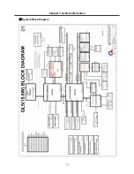
Page 17: ...17 System Block Diagram Chapter 3 System information ...
Page 27: ...27 Ch3 System information g Burn process completed as below and tab OK ...
Page 60: ...60 Ch5 Removing and replacing a part 5 Remove the HDD Shield ...
Page 63: ...63 Ch5 Removing and replacing a part 3 Remove the WLAN Module ...
Page 66: ...66 3 Remove the ODD Ch5 Removing and replacing a part 4 Remove the ODD Bezel Bezel ...
Page 69: ...69 69 Ch5 Removing and replacing a part 5 Remove the Keyboard 6 Remove the Retainer ...
Page 71: ...71 71 Ch5 Removing and replacing a part 3 Remove the Display Module ...
Page 74: ...74 Ch5 Removing and replacing a part 3 Remove the Keyboard deck ...
Page 79: ...79 Ch5 Removing and replacing a part 3 Remove the Mainboard Case ...
Page 86: ...86 Ch5 Removing and replacing a part 3 Remove the Hinge Cap ...
Page 98: ...NLCD07 NLCD05 NLCD09 NLCD03 NLCD01 NLCD04 NLCD08 NLCD02 NWEBC01 ...
Page 100: ...NMINI02 NMINI01 NKDECK01 NKDECK02 NRTN01 NKEYBD01 ...
Page 102: ...NMRY01 NMRY01 NMINI04 NTHMO01 NRBS01 NMINI03 NCPU01 NMLB01 ...
Page 105: ...NCVR02 NCVR03 NCVR01 NHDD02 NHDD01 NBATT01 NODD02 NODD01 NBOTM01 NBOTM03 NHDD03 NBOTM02 ...

