background image

87

Ch5. Removing and replacing a part

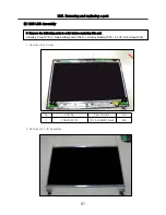
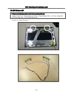
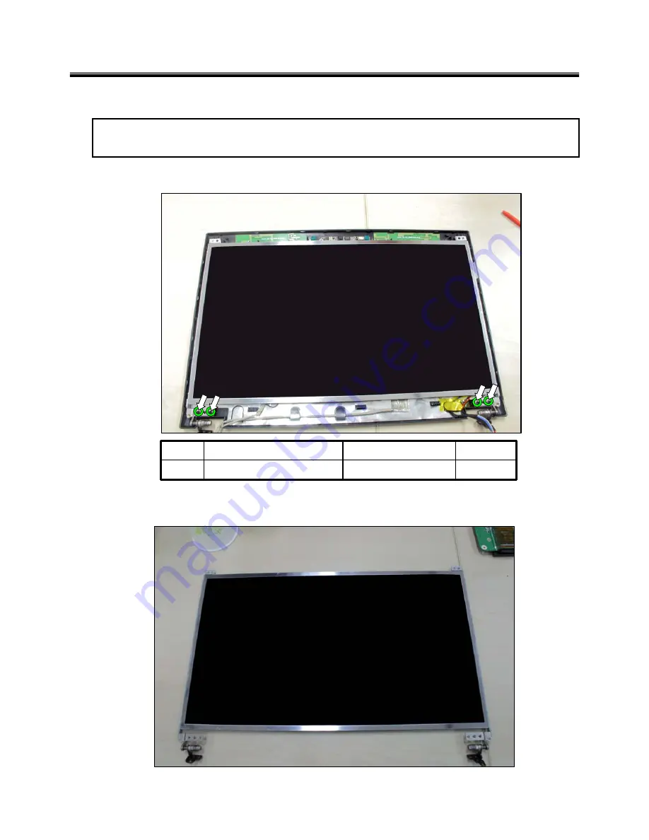
■ 1230 LCD Assembly

1. Remove the 4 Screw.

2. Remove the LCD Assembly.

※ Remove the following parts in order before replacing this part 

a. Battery Pack(1010), b. Retainer/Keyboard (1080), c. Display Module(1090 )  d. LCD Front Case(1220)

No.

FRU No.

Specification

Qty

1

FAB30479701

(M2.5*6.5MM) black

4EA

Summary of Contents for R580 Series U.ARC3BA9

Page 1: ...1 Service Manual Model R580 RB580 R560 RB560 Series P N MFL62539202 REV 18 2011 05 12 Copy Rightⓒ2011 LG Electronic inc DigitalMate Co Ltd LGE Internal use only ...

Page 2: ...on System Block Diagram Fn key combinations Status indicators BIOS Flash BIOS Setup Ch 4 Symptom to part index Power system checkout Numeric error codes Error messages LCD related symptoms Indeterminate problems Ch 5 Removing and replacing a part FRU Ch 6 Part list Part list Exploded view Contents ...

Page 3: ...er you are servicing may have been changed Be extremely careful during write operations such as copying saving or formatting If you select an incorrect drive data or programs can be overwritten Use the following strategy to prevent unnecessary expense for replacing and servicing parts 1 If you are instructed to replacing a part but the replacement does not correct the problem reinstall the origina...

Page 4: ...hrow it into fire or water or short circuit it Dispose of the battery pack as required by local ordinances or regulations Use only the battery in the appropriate parts listing when replacing the battery pack Use of an incorrect battery can result in ignition or explosion of the battery Warning If the LCD breaks and the fluid from inside the LCD gets into your eyes or on your hands immediately was ...

Page 5: ...ed covers and other parts in a safe place away from all personnel while you are servicing the machine Keep your tool box away from walk areas so that other people will not trip over it Do not wear loose clothing that can be trapped in the moving parts of a machine Make sure that your sleeves are fastened or rolled up above your elbows If your hair is long fasten it Insert the ends of your necktie ...

Page 6: ...r before 1 Performing a mechanical inspection 2 Working near power supplies 3 Removing or installing main units Before you start to work on the machine unplug the power cord If you cannot unplug it ask the customer to power off the wall box that supplies power to the machine and to lock the wall box in the off position If you need to work on a machine that has exposed electrical circuits observe t...

Page 7: ... look carefully for possible hazards in your work area Examples of these hazards are moist floors non grounded power extension cables power surges and missing safety grounds Do not touch live electrical circuits with the reflective surface of a plastic dental mirror The surface is conductive such touching can cause personal injury and machine damage Do not service the following parts with the powe...

Page 8: ...rds such as loose or missing hardware Refer to the following checklist and begin the checks with the power off and the power cord disconnected Checklist 1 Check exterior covers for damage loose broken or sharp edges 2 Power off the computer Disconnect the power cord 3 Check the power cord for a A third wire ground connector in good condition Use a meter to measure third wire ground continuity for ...

Page 9: ...he part from touching your clothing Most clothing retains a charge even when you are wearing a wrist strap 4 Use the black side of a grounded work mat to provide a static free work surface The mat is especially useful when handling ESD sensitive devices 5 Select a grounding system such as those listed below to provide protection that meets the specific service requirement Note The use of a groundi...

Page 10: ...e DVD ROM drive or the other optical storage device could result in exposure to hazardous laser radiation There are no serviceable parts inside those drives Do not open Danger Emits visible and invisible laser radiation when open Do not stare into the beam do not view directly with optical instruments and avoid direct exposure to the bean 1 5 Backup Standby RTC battery safety information When repl...

Page 11: ...cur for a variety of reasons that have nothing to do with a hard ware defect such as cosmic radiation electrostatic discharge or software errors Consider replacing a FRU only when a problem recurs If you suspect that a FRU is defective clear the error log and run the test again If the error does not recur do not replace the FRU Be careful not to replace a non defective FRU What to do first You mus...

Page 12: ...age caused foreign material in the diskette drive Diskette drive damage caused by pressure on the diskette drive cover or by the insertion of a diskette with multiple labels Damaged or bent diskette eject button Fusses blown by attachment of a non supported device Forgotten computer password making the computer unusable Sticky keys caused by spilling a liquid onto the keyboard The following sympto...

Page 13: ...rt 5 HDMI Port 6 e SATA Port USB combo 7 Multi Card Slot xD SD MS MS Pro 8 Express Card Slot 9 Microphone Port 10 Headphone Port 11 USB Port 12 Optical Disk Drive 13 Power Port 14 Kensington lock Chapter 2 Locations Ch2 Locations Left View Right View ...

Page 14: ...one May vary depending on model 17 Smart Cam May vary depending on model 18 Power Button 19 Mute Button 20 Volume Down Button 21 Volume Up Button 22 SRS Button 23 Keyboard 24 Touchpad 25 Stereo speaker Front Back Front View 15 Fan louvers ...

Page 15: ...he type depend on the notebook PC model LCD 15 6 HD 1600 x 900 w LED Backlight TFT Color LCD 15 6 HD 1366 x 768 w LED Backlight TFT Color LCD Some models are equipped with the Glare type LCD featuring enhanced sharpness This type of LCD appears to glare more than other types but it is a normal phenomenon in the Glare type The size and the resolution rate of the LCD depend on the notebook PC model ...

Page 16: ...rge graphic data like 3D graphics The size of the utilized memory is determined by the Video Memory size and System Memory Sizes If TurboCache technology is applied to the Graphics Memory the System Memory can allot up to 576MB out of 512MB and up to 2815MB out of 4096MB for large graphic data The specifications may differ depending on the model type and the video driver Sound Realtek High Definit...

Page 17: ...17 System Block Diagram Chapter 3 System information ...

Page 18: ...installed in some models Through hot key settings in the OSD Tray menu the user can customize Fn F6 features Default setting is for all wireless devices incl Wireless LAN and Bluetooth ON Off Fn F7 Monitor toggle If you have an external monitor connected to the computer press Fn F7 keys to rotate the display mode from LCD only to Monitor only to LCD Monitor both in order Fn F8 Switches between the...

Page 19: ... on the system that has entered the Hibernates mode or been turned off after a low battery alarm the system will not be turned on but the lamp will blink three times 3 Hard Disk Drive Lamp The lamp is turned on when the HDD is running Do not turn off the power forcibly while the hard disk drive lamp is on Otherwise the data may get impaired 4 Num Lock lamp You can activate Num Lock feature by pres...

Page 20: ...ss LAN Bluetooth is not connected but Wireless Radio is on Blinking every 3 4 seconds An access Point is being searched for to connect Wireless LAN Bluetooth On An access point is being searched for or Wireless LAN Bluetooth is connected The Wireless LAN Bluetooth lamp may operate differently depending on model type The Wireless LAN card and the Bluetooth device are optional and so it may not be s...

Page 21: ...OS Setup How to update flash Rom in Dos 1 Create boot up flash update USB Device FDD USB Memory 2 Copy BIOS Flash software to the flash update USB Device FDD USB Memory 3 Connect the USB Device for USB Port 4 Press F12 Key while the LG LOGO appears 5 A while later the system setup home screen appears 6 Type in go bat x_xxx is Model Name BIOS version 7 You can see the BIOS flash process as below Ch...

Page 22: ...22 10 Press F2 Key then you can see the BIOS SETUP UTILITY screen as below 11 It selects the Load Optimal Dafault and it summons a BIOS settings at initial value Ch3 System information ...

Page 23: ...23 12 It selects the Exit Saving Change and it stores system a settings and the reboot Ch3 System information ...

Page 24: ...ervice com when BIOS should be updated 2 BIOS will include both System BIOS and EC Embedded Controller BIOS 3 Service center can download BIOS file from GCSC and update BIOS according to below procedure 4 Service center will make Bootable Image CD with Image file iso as below a Insert empty disc to CD RW Drive and start Nero StartSmart b Select Nero Express ...

Page 25: ...25 Ch3 System information c Select Disc Image or Saved Project d Select File Format as Image Files iso ...

Page 26: ...26 Ch3 System information e Open Image File iso which is sent from LGE f Tab Burn then burning will be started ...

Page 27: ...27 Ch3 System information g Burn process completed as below and tab OK ...

Page 28: ...PC and Turn it on then PC will boot by DOS mode as below If the EC is not correct or old version then automatically update EC first and reboot again 2 Select Boot mode then press Enter Key 3 Type in LOGO SETTING at the WIP ID then press Enter key You must use Capital Letter ...

Page 29: ...Letter You can see the Model Name in ID Label at the bottom Case of PC M N LMXX XXXX 5 Type in Serial No at the WIP ID then press Enter key You must use Capital Letter You can see the Serial No in ID Label at the bottom Case of PC S N 412KIXXXXXXXX 13digits 6 You can see the BIOS flash process as below ...

Page 30: ...30 Ch3 System information 5 After flashing is completed you can see the PASS on your screen and reboot your PC ...

Page 31: ...system environment hardware configurations power saving mode etc Open the BIOS Setup Utility in the following situations 1 to change the BIOS setup 2 to replace the backup battery 3 system configuration error occurs 4 to change the boot order 5 to set change a password Press the power button When the LG logo appears on the screen press and enter the BIOS Setup Utility Ch3 System information ...

Page 32: ...ted Select Menu Move to another menu Change Values Change the value of a selected item Load Default Configuration Display Setup Confirmation window Press Enter to load default configuration Select Sub Menu Some items have sub menus Display the sub menu for a selected item Save and Exit Display Setup Confirmation window Press Enter to save and exit Exit In a sub menu press Esc to move to the previo...

Page 33: ...the description of the drive connected to the SATA port To change the settings of the connected drive click Enter after selecting this option CD ROM DVD ROM This shows the description of the drive connected to the ODD drive port To change the settings of the connected drive click Enter after selecting this option Main menu Ch3 System information ...

Page 34: ...on technology AC Mode Fan always on Select any of Normal Silent and Cool for the operating speed of CPU cooling fan for AC power DC Mode Fan always on Select any of Normal Silent and Cool for the operating speed of CPU cooling fan for DC power Mute button option Set whether or not to support the Mute function Fn F9 during the system startup Internal Devices Configurations Set whether or not to use...

Page 35: ...the system is turned on any other user cannot change the BIOS settings without entering the specified password User Password Set User Password is for setting the password lower than the one set in Set Supervisor Password Set User Password is active only when the supervisor password is set Set Supervisor Password Set Supervisor Password Set User Password Set User Password Set All Hdd Password Set t...

Page 36: ...Quick Boot Set whether or not to use Quiet Boot PXE Boot to LAN Set whether or not to use the HDD password Boot Device Priority Select the desired device drive by using the arrow buttons and change its booting sequence by using the or key ...

Page 37: ...al number of the product SLP 2 0 The Vista OS protection device will be able to use from LG CPU Type This shows the type of the CPU installed in the system L2 Cache RAM This shows the size of L2 Cache RAM for the CPU Total Memory This is for display only This shows size of system memory Slot 1 3 Memory This shows the size of the memory installed in the memory slot ...

Page 38: ... the Setup menu to the factory default settings When it is selected or F9 key is pressed the confirmation message appears Click Yes to change the settings Load Custom Defaults This returns the user defined settings for the parameters in the Setup menu Save Custom Defaults This saves the desired values for each parameter in the Setup menu Discard Changes This returns to the factory default settings...

Page 39: ... all Security Platform Users for one or multiple Security Platform computers Also contains computer identification and user identification which are used to match computers and users during the restoration process Manually written Backup Archive e g SPBackupArchive xml Created by Security Platform User Contains credentials and settings of one Security Platform User for one Security Platform comput...

Page 40: ...ion settings are included in both automatically written Backup Archives and manually written Backup Archives PSD backup file e g SpPSDBackup fsb A backup copy of the PSD image file may be created during a Security Platform User s manual backup Restoration Cases Depending on the type of emergency there are different restoration cases Restoration Case Affected Restoration Scope Broken hard disk or l...

Page 41: ...d no Emergency Recovery data needs to be restored then a user can perform restoration without preparation by an administrator Settings Tool Backup Restore Backup With this page you can configure automatic Security Platform backups The following table gives hints on how to use this wizard page Wizard Page Element Explanation Backup location Browse Security Platform credentials and settings will be ...

Page 42: ...re to set up automatic Security Platform backups Infineon Security Platform Initialization Wizard will be started This feature is only available if the current user account has administrative rights Click here to start a manual backup of your Security Platform Settings and credentials If you have configured Personal Secure Drive PSD you can backup your PSD too The Infineon Security Platform Backup...

Page 43: ... Power off the computer 6 Disconnect the AC adapter and install the charged battery pack 7 Check that the battery pack supplies power when you power on the computer If you suspect a power problem see the appropriate one of the following power supply checkouts 1 Checking the AC adapter 2 Checking the operational charging 3 Checking the battery pack 4 Checking the backup battery Checking the AC adap...

Page 44: ...the plug of the AC adapter cable See the following figure 3 If the voltage is not correct remove the power code form AC adapter 4 10 seconds later connect the power code then measure the output voltage 5 If the voltage is not correct change the AC adapter 2 1 Pin Voltage V dc 1 18 05 19 95 2 Ground Ch4 Symptom to part index ...

Page 45: ...arge battery pack when its temperature is below 0 or above 75 Checking the battery pack 1 Open the Power Meter window by clicking Start Control Panel Power Options and then check the total power remains Battery charging does not start until the power Meter shows that less than 95 of the total power remains under this condition the battery pack can charge to 100 of its capacity This protects the ba...

Page 46: ... When this happens you can perform the full discharge charge to improve the capacity You should perform periodic full discharge charge once every 30 60 days You should always use the battery until its power is low then fully charge the battery 3 Trickle charge If the temperature of the battery pack drops below 10 the trickle charging begins The trickle charging may take 32 hours for the battery pa...

Page 47: ...f the voltage is still less than 11 1 V DC after recharging replace the battery 4 If the voltage is more than 11 1 V DC measure the resistance between battery terminals 1 and 2 The resistance must be 2 to 4 typically 3 5 If the resistance is not correct replace the battery pack If the resistance is correct replace the system board Ch4 Symptom to part index Note Battery is an expendable supplier so...

Page 48: ... the auxiliary input device 0212 Keyboard Controller Failed System board 0220 Monitor type error Monitor type does not match the one specified in CMOS Load Setup Defaults in BIOS Setup Utility 0230 System RAM error System RAM Failed at offset 1 DIMM 2 System board 0231 Shadow RAM error Shadow RAM failed at offset System board 0232 Extended RAM error Extended RAM Failed at address line 1 DIMM 2 Sys...

Page 49: ... Utility 2 DIMM 3 System board 0281 Memory Size found by POST differed from EISA CMOS Load Setup Defaults in BIOS Setup Utility 02B0 Diskette drive A error Set up the diskette type in BIOS Setup Utility 02B1 Diskette drive B error Set up the diskette type in BIOS Setup Utility 02B2 Incorrect drive A type Floppy diskette drive error 1 Floppy diskette drive 2 External FDD cable 3 I O card 02B3 Incor...

Page 50: ... BIOS Setup Utility 2 System board 0615 Com B configuration changed 1 Load Setup Defaults in BIOS Setup Utility 2 System board 0616 Com B configuration error 1 Load Setup Defaults in BIOS Setup Utility 2 System board 0617 Floppy configuration changed 1 Load Setup Defaults in BIOS Setup Utility 2 System board 0618 Floppy configuration error 1 Load Setup Defaults in BIOS Setup Utility 2 System board...

Page 51: ...kup battery 3 System board Operating System not found 1 Check that the operating system has no failure and is installed correctly 2 Enter BIOS Setup Utility and see whether the hard disk drive and the diskette drive are properly identified 3 Reset the hard disk drive 4 Reinstall the operating system 5 Diskette drive 6 Hard disk drive 7 System board Hibernation error 1 Restore the system configurat...

Page 52: ...mode switch if it is pressed by something 4 Check the System is in standby or hibernation mode LCD backlight not working LCD too dark LCD brightness cannot be adjusted 1 Reconnect inverter to the board connector 2 Replace inverter 3 LCD Assembly 4 System board LCD color cannot be adjusted LCD screen abnormal Characters missing pixels LCD screen unreadable Wrong color displayed 1 Reset all LCD conn...

Page 53: ...RU 3 Remove or disconnected all of the following devices a Non LG devices b Printer mouse and other external devices c Battery pack d PC cards e ODD CD ROM Combo drive or FDD drive in the Bay f Hard disk drive Note Use the other memory card because it needs when operating computer 4 Power on the computer 5 Determine whether the problem has changed 6 If the problem does not recur reconnect the remo...

Page 54: ...any FRU power off the computer unplug all power cords from electrical outlets remove the battery pack and then disconnect any interconnecting cables Caution Before the computer is powered on after FRU replacement make sure that all screws springs and other small parts are in place and are not loose inside the computer Verify metal flakes can cause electrical short circuits Ch5 Removing and replaci...

Page 55: ...55 55 1010 Battery Pack 1 Push the battery latch in the direction shown below then slide the battery pack out of the slot Ch5 Removing and replacing a part 2 Remove the Battery Pack ...

Page 56: ...56 1020 Memory Remove the following parts in order before replacing this part a Battery Pack 1010 Ch5 Removing and replacing a part 1 Remove the 3 screw 2 Remove the Memory Cover ...

Page 57: ...57 3 Remove the Hook Ch5 Removing and replacing a part Hook Hook Hook Hook 4 Remove the Memory ...

Page 58: ...58 1030 HDD Remove the following parts in order before replacing this part a Battery Pack 1010 Ch5 Removing and replacing a part 1 Remove the 2 Screw 2 Remove the HDD Cover ...

Page 59: ...59 Ch5 Removing and replacing a part No FRU No Specification Qty 1 FAB30479801 M3 0 3 0MM White 4EA 4 Remove the 4 Screw 3 Remove the HDD ...

Page 60: ...60 Ch5 Removing and replacing a part 5 Remove the HDD Shield ...

Page 61: ...61 1040 Wi Fi Cover Remove the following parts in order before replacing this part a Battery Pack 1010 Ch5 Removing and replacing a part 1 Remove the 1 Screw 2 Remove the Wi Fi Cover ...

Page 62: ...owing parts in order before replacing this part Battery Pack 1010 b Wi Fi Cover 1040 Ch5 Removing and replacing a part 1 Remove the Antenna Cable 2 Screw 2 Remove the 1 Screw No FRU No Specification Qty 1 FAB30208501 M2 0 3 0MM White 1EA ...

Page 63: ...63 Ch5 Removing and replacing a part 3 Remove the WLAN Module ...

Page 64: ... part 1060 Turbo Memory Remove the following parts in order before replacing this part Battery Pack 1010 b Wi Fi Cover 1040 1 Remove the 1 Screw 2 Remove the Turbo Memory No FRU No Specification Qty 1 MM20030ICI3 M2 0 3 0MM White 1EA ...

Page 65: ...s in order before replacing this part a Battery Pack 1010 1 Remove the 1 Screw Ch5 Removing and replacing a part No FRU No Specification Qty 1 FAB30479701 M2 5 6 5MM black 1EA 2 It uses JIG and pushes separates with arrow ticket direction ...

Page 66: ...66 3 Remove the ODD Ch5 Removing and replacing a part 4 Remove the ODD Bezel Bezel ...

Page 67: ...lacing this part a Battery Pack 1010 1080 Retainer Keyboard 1 Remove the 6 Screw 2 It uses JIG and it removes the Hooks Ch5 Removing and replacing a part No FRU No Specification Qty 1 FAB30479701 M2 5 6 5MM black 3EA 2 FAB30255101 M2 5 3 0MM White 3EA ...

Page 68: ...68 Ch5 Removing and replacing a part 3 Remove the 2 Screw 4 Remove the Retainer Keyboard Cable No FRU No Specification Qty 1 FAB30255101 M2 5 3 0MM black 2EA Cable Cable ...

Page 69: ...69 69 Ch5 Removing and replacing a part 5 Remove the Keyboard 6 Remove the Retainer ...

Page 70: ...acing this part a Battery Pack 1010 b Retainer Keyboard 1080 1090 Display Module 1 Remove the 4 Screw 2 Remove the Cable Ch5 Removing and replacing a part No FRU No Specification Qty 1 FAB30479701 M2 5 6 5MM black 2EA 2 FAB30255101 M2 5 3 0MM White 2EA ...

Page 71: ...71 71 Ch5 Removing and replacing a part 3 Remove the Display Module ...

Page 72: ...g parts in order before replacing this part a Battery Pack 1010 b Retainer Keyboard 1080 c Display Module 1090 1100 Button Sub Board 1 Remove the 1 Screw 2 Remove the Button Sub Board Ch5 Removing and replacing a part Cable ...

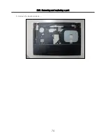
Page 73: ... it removes the Keyboard deck 1 Remove the 10 Screw No FRU No Specification Qty 1 FAB30479701 M2 5 6 5MM black 10EA Remove the following parts in order before replacing this part a Battery Pack 1010 b Retainer Keyboard 1080 c Display Module 1090 d Button Sub Board 1100 ...

Page 74: ...74 Ch5 Removing and replacing a part 3 Remove the Keyboard deck ...

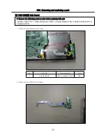
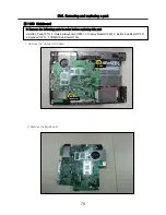
Page 75: ...arts in order before replacing this part a Battery Pack 1010 b Retainer Keyboard 1080 c Display Module 1090 d Button Sub Board 1100 e Keydeck 1120 1 Remove the Cable and 2 Screw 2 Remove the USB R Sub Board No FRU No Specification Qty 1 FAB30248901 M2 5 6 5MM black 2EA Cable Cable ...

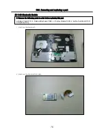
Page 76: ...40 Bluetooth Module Remove the following parts in order before replacing this part a Battery Pack 1010 b Retainer Keyboard 1080 c Display Module 1090 d Button Sub Board 1100 e Keydeck 1120 1 Remove the Bluetooth 2 Remove the Bluetooth Module ...

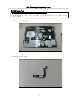
Page 77: ...150 Touch Pad Remove the following parts in order before replacing this part a Battery Pack 1010 b Retainer Keyboard 1080 c Display Module 1090 d Button Sub Board 1100 e Keydeck 1120 1 Remove the 1 Connector Connector 2 Remove the Touch Pad ...

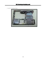
Page 78: ...ove the following parts in order before replacing this part a Battery Pack 1010 b Retainer Keyboard 1080 c Display Module 1090 d Button Sub Board 1100 e Keydeck 1120 f USB R Sub Board 1130 1 Remove the Connector Cable 2 Remove the Mainboard Cable Connector ...

Page 79: ...79 Ch5 Removing and replacing a part 3 Remove the Mainboard Case ...

Page 80: ...ng and replacing a part 1170 CPU GPU Fan Assembly Remove the following parts in order before replacing this part a Battery Pack 1010 b Memory 1020 1 Remove the 7 Screw 2 Remove the CPU GPU Fan Assembly Fix Fix Cable ...

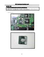
Page 81: ...1180 CPU Remove the following parts in order before replacing this part a Battery Pack 1010 b Retainer Keyboard 1080 c Display Module 1090 d Button Sub Board 1100 e Keydeck 1120 f Mainboard 1160 g CPU GPU Fan Assembly 1170 1 Remove the CPU ...

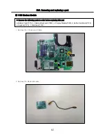
Page 82: ...ule 1 Remove the 2 Screw and Cable 2 Remove the Modem Module Remove the following parts in order before replacing this part a Battery Pack 1010 b Retainer Keyboard 1080 c Display Module 1090 d Button Sub Board 1100 e Keydeck 1120 f Mainboard 1160 Cable ...

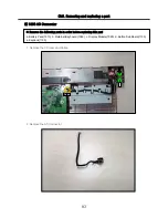
Page 83: ...AC Connector 1 Remove the 2 Screw and Cable 2 Remove the AC Connector Remove the following parts in order before replacing this part a Battery Pack 1010 b Retainer Keyboard 1080 c Display Module 1090 d Button Sub Board 1100 e Keydeck 1120 Cable ...

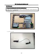
Page 84: ...210 Speaker 1 Remove the 2 Screw 2 Remove the Speaker Remove the following parts in order before replacing this part a Battery Pack 1010 b Retainer Keyboard 1080 c Display Module 1090 d Button Sub Board 1100 e Keydeck 1120 f Mainboard 1160 ...

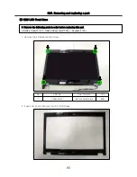
Page 85: ...move the 4 Rubber and 4 Screw 2 It uses JIG and it removes the LCD Front Case No FRU No Specification Qty 1 FAB30479701 M2 5 6 5MM black 4EA Remove the following parts in order before replacing this part a Battery Pack 1010 b Retainer Keyboard 1080 c Keydeck 1120 ...

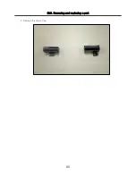
Page 86: ...86 Ch5 Removing and replacing a part 3 Remove the Hinge Cap ...

Page 87: ...Remove the 4 Screw 2 Remove the LCD Assembly Remove the following parts in order before replacing this part a Battery Pack 1010 b Retainer Keyboard 1080 c Display Module 1090 d LCD Front Case 1220 No FRU No Specification Qty 1 FAB30479701 M2 5 6 5MM black 4EA ...

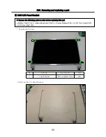
Page 88: ... LCD Panel Bracket No FRU No Specification Qty 1 FAB30208501 M2 0 3 0MM black 4EA 1 Remove the 4 Screw Remove the following parts in order before replacing this part a Battery Pack 1010 b Retainer Keyboard 1080 c Display Module 1090 d LCD Front Case 1220 e LCD Assembly 1230 ...

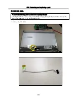
Page 89: ...250 LCD Cable 1 Remove the LCD Cable Remove the following parts in order before replacing this part a Battery Pack 1010 b Retainer Keyboard 1080 c Display Module 1090 d LCD Front Case 1220 e LCD Assembly 1230 f LCD Panel Bracket 1240 Cable ...

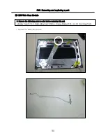
Page 90: ...nd replacing a part 1260 Web Cam Module 1 Remove the Web Cam Module Remove the following parts in order before replacing this part a Battery Pack 1010 b Retainer Keyboard 1080 c Display Module 1090 d LCD Front Case 1220 ...

Page 91: ...70 Wireless ANT 1 Remove the Wireless Module Remove the following parts in order before replacing this part a Battery Pack 1010 b Retainer Keyboard 1080 c Display Module 1090 d LCD Front Case 1220 e LCD Assembly 1230 f LCD Panel Bracket 1240 ...

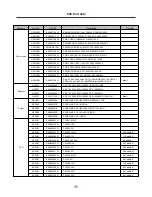
Page 92: ...01 10 30 add 09 QL5A MB INT N10M SAM512 W O CPU DDR3 GeForce G 210M EBR63324110 NMLB01 10 30 add 09 QL5A MB INT N10M HYN512 W O CPU DDR3 GeForce G 210M EBR63324109 NMLB01 QL5 MB INT N10P GE1 SAM1G W O CPU MODEM DDR2 GeForce GT 130M EBR63154505 NMLB01 QL5 MB ASSY INT N10P HYN1G W O CPU MODEM DDR2 GeForce GT 130M EBR63154506 NMLB01 QL5 MB INT N10P GE1 C1 SAM1G W O CPU DDR2 GeForce GT 130M EBR6315440...

Page 93: ...A CNY AEW72909405 NKEYBD01 K B NORDIC QL5 AEQL5N00 REV3A CNY AEW72909407 NKEYBD01 K B SPANISH QL5 AEQL5P00 REV3A CNY AEW72909406 NKEYBD01 KB ARABIC QL5 AEQL5Q00 REV3A CNY AEW72909403 NKEYBD01 K B HEBREW QL5 AEQL5V00 REV3A CNY AEW72909409 NKEYBD01 9 30 add 09 K B French QL5 AEQL5F00010 black chicony AEW72909411 NKEYBD01 BLUETOOTH2 1 EDR USB MODULE QBT400UB 01P EAT56371601 NMINI01 MiniCard Bluetooth...

Page 94: ...ODULE ASSY 35W DIS FOX AJJ73040001 NTHMO01 QL5A THERMAL MODULE ASSY 35W DIS RSI AJJ73040002 NTHMO01 QL5A THERMAL MODULE ASSY 35W DIS FCN AJJ73040003 NTHMO01 KB COVER CAPACITY ASSY_R580 ABQ72943601 NRTN01 Retainer KB COVER NORMAL ASSY_R560 ABQ72943701 NRTN01 Function Button Board_R560 EBR63115701 NRTN02 11 10 add 09 CABLE FFC QL5 BB MB 6P 51 5MM 3A 60V EAD61073901 NRTN03 Keyboard Deck Assy with tou...

Page 95: ... plate ABQ72944801 NLCD05 Front Case assy without web cam lens without Name plate ABQ72944802 NLCD05 Name Label R580 Consummer MEZ62198001 NLCD06 Name Label R560 Consummer MEZ62198301 NLCD06 Name Label RB560 KOREA Commecial MEZ62198501 NLCD06 Name Label RD580 FREE DOS MEZ62198601 NLCD06 Name Label RD560 FREE DOS MEZ62198701 NLCD06 HINGE CAP LEFT QL5 MCK62490801 NLCD07 12 3 add 09 HINGE CAP LEFT QL...

Page 96: ... NCPU01 6 12 add 09 P7350 2G EAN52856301 NCPU01 11 5 add 09 P7450 2 13G EAN60661401 NCPU01 8 17 add 09 P7550 2 26G EAN60739001 NCPU01 8 17 add 09 P8700 2 53G EAN60666201 NCPU01 8 17 add 09 P8800 2 66G EAN60778501 NCPU01 Remark Description LG P N Loc No Category Brazil Plug LP 26A Connector LS 15 1 8M NONE 250V 10A H03VV F 0 75mm 2 x 3C BLACK INMETRO Brazil NBR 14136 N EAD55718611 NPWCD01 PWR CORD ...

Page 97: ...ll model Intel Pentium Processor 2009 320797 001 MEZ62085802 NLAB02 CPU Label All model Intel Centrino Processor Technology 2009 320821 001 MEZ62085701 NLAB02 CPU Label All model Intel Centrino 2 Processor Technology 2009 320817 001 MEZ62085201 NLAB02 CPU Label All model Intel Core2 Duo Processor 2009 320781 001 MEZ62085303 NLAB02 POP LABEL KOREA MEZ61946901 NLAB03 POP LABEL GLOBAL MEZ61946902 NLA...

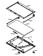
Page 98: ...NLCD07 NLCD05 NLCD09 NLCD03 NLCD01 NLCD04 NLCD08 NLCD02 NWEBC01 ...

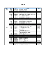
Page 99: ...nge_LG _CI model ABQ72944009 NLCD04 12 3 add 09 QL5A rear case normal black_Xnote _CI model ABQ72944008 NLCD04 12 3 add 09 QL5A rear case normal black_LG _CI model ABQ72944007 NLCD04 QL5 LCD COVER ASSY HSDPA WH LG ABQ72944001 NLCD04 QL5 LCD COVER ASSY HSDPA BK LG ABQ72944002 NLCD04 QL5 LCD COVER ASSY STANDARD WH XNOTE ABQ72944004 NLCD04 QL5 LCD COVER ASSY STANDARD BK XONTE ABQ72944006 NLCD04 QL5 L...

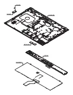
Page 100: ...NMINI02 NMINI01 NKDECK01 NKDECK02 NRTN01 NKEYBD01 ...

Page 101: ... B S EBM51208101 NMINI03 WLAN 802 11ABGN 512AN_MMWG ROK B S EBM51207601 NMINI03 WLAN 802 11 B G N 9WEM302QCF01Q EBM54120901 NMINI03 WLAN 802 11 B G N 9WEM302QCE02Q EBM54120701 NMINI03 Bluetooth Cable 10PIN REV2A 300V EAD60698101 NMINI02 BLUETOOTH2 1 EDR USB MODULE QBT400UB 01P EAT56371601 NMINI01 MiniCard 9 30 add 09 K B French QL5 AEQL5F00010 black chicony AEW72909411 NKEYBD01 K B HEBREW QL5 AEQL...

Page 102: ...NMRY01 NMRY01 NMINI04 NTHMO01 NRBS01 NMINI03 NCPU01 NMLB01 ...

Page 103: ...DR3 EBR63324112 NMLB01 10 30 add 09 QL5A MB ASSY INT GM45 W O CPU DDR3 EBR63324111 NMLB01 10 30 add 09 QL5A MB INT N10M SAM512 W O CPU DDR3 GeForce G 210M EBR63324110 NMLB01 10 30 add 09 QL5A MB INT N10M HYN512 W O CPU DDR3 GeForce G 210M EBR63324109 NMLB01 QL5 MB INT N10P GE1 SAM1G W O CPU MODEM DDR2 GeForce GT 130M EBR63154505 NMLB01 QL5 MB ASSY INT N10P HYN1G W O CPU MODEM DDR2 GeForce GT 130M ...

Page 104: ...09201 NCPU01 6 8 add 10 T4500 2 30GHz EAN61016401 NCPU01 6 12 add 09 T6400 2GHZ EAN60661201 NCPU01 6 12 add 09 T6500 2 1G EAN60738901 NCPU01 7 28 add 09 T6600 2 2G EAN60661101 NCPU01 6 12 add 09 T6670 2 2GHZ EAN60809301 NCPU01 6 12 add 09 P7350 2G EAN52856301 NCPU01 11 5 add 09 P7450 2 13G EAN60661401 NCPU01 8 17 add 09 P7550 2 26G EAN60739001 NCPU01 8 17 add 09 P8700 2 53G EAN60666201 NCPU01 8 17...

Page 105: ...NCVR02 NCVR03 NCVR01 NHDD02 NHDD01 NBATT01 NODD02 NODD01 NBOTM01 NBOTM03 NHDD03 NBOTM02 ...

Page 106: ...PM FUJITSU EAZ60666904 NHDD01 500GB SATA 5400RPM HITACHI EAZ60666004 NHDD01 320GB SATA 5400RPM HITACHI EAZ60666003 NHDD01 320GB SATA 5400RPM FUJITSU EAZ60666903 NHDD01 250GB SATA 5400RPM FUJITSU EAZ60666902 NHDD01 250GB SATA 5400RPM HITACHI EAZ60666002 NHDD01 6 10 add 09 160GB SATA 5400RPM HITACHI EAZ60666001 NHDD01 6 10 add 09 160GB SATA 5400RPM FUJITSU EAZ60666901 NHDD01 HDD MINI CARD DOOR ASSY_...

Page 107: ...C Jack cable assy EAD60684401 NBOTM04 Audio USB suboard Cable EAD60840101 NBOTM03 AUDIO USB Subboard ASSY EBR63115501 NBOTM02 Case Assy Racer15 BOTTOM BK DIS wo RJ11 AFP72919108 NBOTM01 Case Assy Racer15 BOTTOM BK UMA wo RJ11 AFP72919107 NBOTM01 Case Assy Racer15 BOTTOM BK DIS w RJ11 AFP72919106 NBOTM01 Case Assy Racer15 BOTTOM BK UMA w RJ11 AFP72919105 NBOTM01 Case Assy Racer15 BOTTOM White DIS w...

Reviews: