2-9
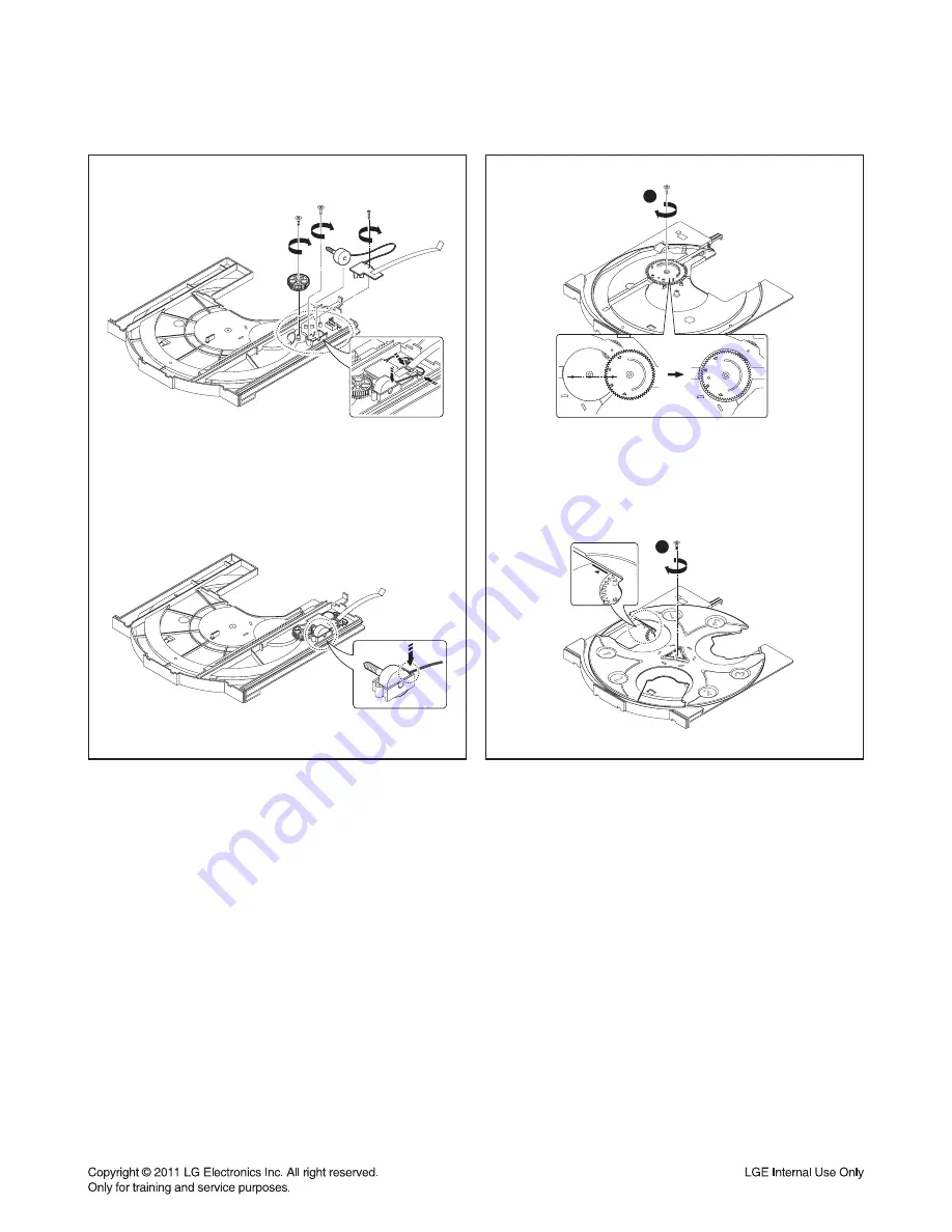
Figure 7
2
1
Figure 8
7) After setting the Gear Tray, Tray Motor Assy and
Loading PCB Assy on the Tray Loading, tighten the
screw.
8) Assemble the Gear Tray CAM on the Tray Loading
and set the Tray Disc.
(When assembling, check the location of the Gear Tray
CAM and Tray Disc as shown in the Figure)
ORDER OF ASSEMBLY FOR MECHANISM DECK
Summary of Contents for RCS606F
Page 25: ...2 16 A60 4 SPEAKER SECTION 4 1 FRONT SPEAKER RCS606F ...
Page 26: ...2 17 A90A LED A90 4 2 PASSIVE SUBWOOFER RCS606W ...
Page 27: ...2 18 MEMO ...
Page 69: ...3 42 MEMO ...
Page 88: ...3 79 3 80 PRINTED CIRCUIT BOARD DIAGRAMS 1 MAIN P C BOARD TOP VIEW ...
Page 89: ...3 81 3 82 MAIN P C BOARD BOTTOM VIEW ...
Page 91: ...3 85 3 86 3 VFD P C BOARD BOTTOM VIEW ...
Page 92: ...3 87 3 88 4 VOLUME P C BOARD ...
Page 93: ...3 89 3 90 6 IPOD P C BOARD TOP VIEW BOTTOM VIEW 5 USB MIC P C BOARD TOP VIEW BOTTOM VIEW ...


