3-9
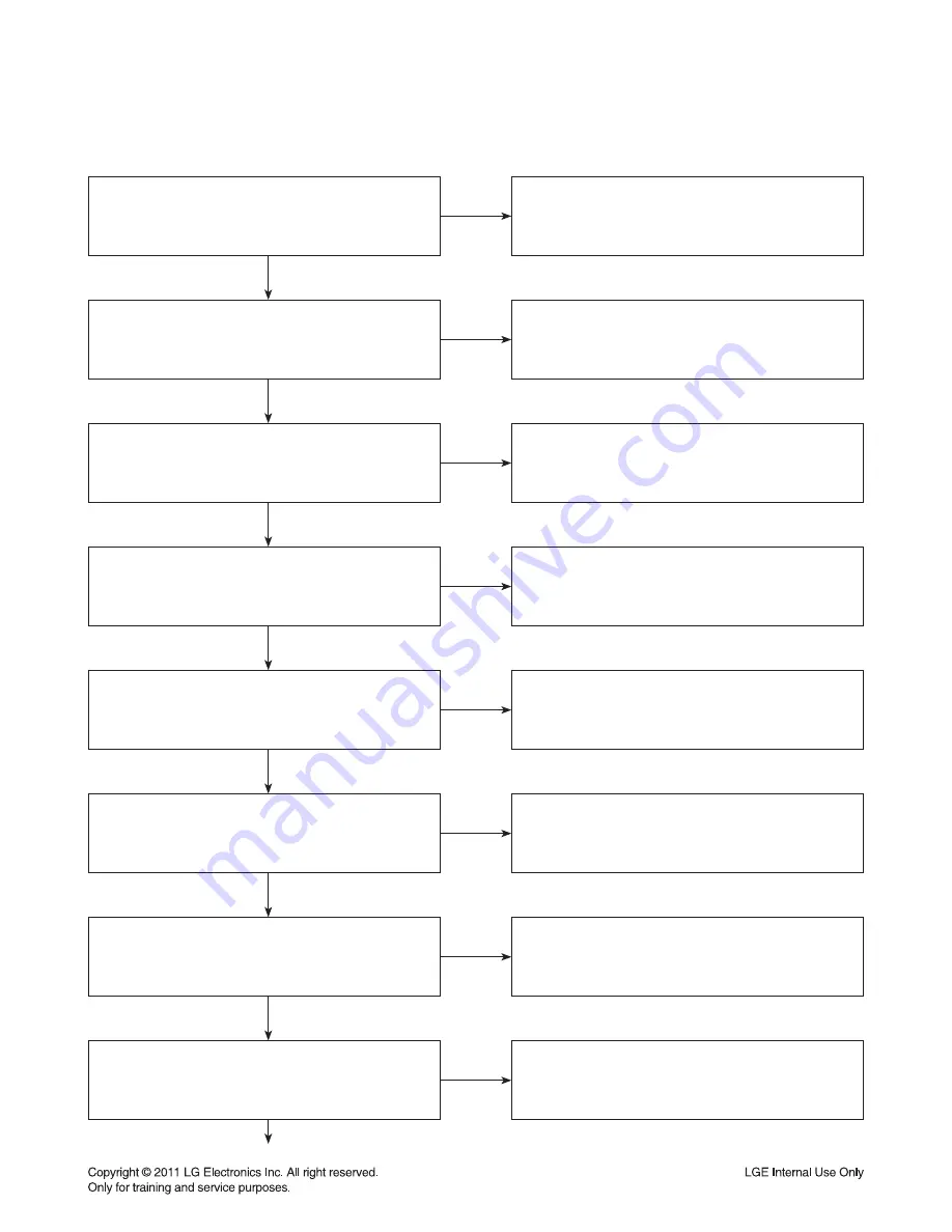
Does the customer select correctly
the USB function he or she wants to listen to?
Make sure to insert a USB on the USB ports
on the bottom of the unit.
YES
NO
Is “USB” displayed on VFD?
Make sure to select the USB function
pressing the CD/USB button.
YES
NO
Does the unit display “SELECTED” on VFD
when a USB is inserted into the USB port?
When “No USB” is displayed,
make sure that the customer uses the recommended
USB which support USB2.0 or USB1.1.
YES
NO
Does the customer use the supported
mp3 or WMA music files on the disc?
Check if it is the playable disc or not.
Make sure that the file extensions are
“.mp3”or “.wma”.
YES
NO
When the unit searches music files in a USB,
are the following messages displayed on VFD?
“SELECTED” “TRACKING #” and “TIME”
Make sure to check the compatible USB device
and the supported MP3/WMA music file requirement.
Refer to the owner’s manual.
YES
NO
After selecting a track number using the SCAN button,
press PLAY button and turn the master volume
clockwise for the volume up.
The volume level LEDs around the master volume
will be turned on more and more
while turning it clockwise for the volume up.
YES
NO
Are the sound spectrum level
on the left and right side of the front panel
being changed up and down
according to the sound input gain?
The sound spectrum level will be turned on/off
repeatedly at regular intervals. A speaker cable
might be short-circuited with the chassis ground.
Be careful not to be shorted each other.
YES
YES
NO
Are the speaker cables connected correctly
between the speaker terminals on the unit
and the speakers?
Make sure to connect the cables
to each specified connector tightly on the unit.
Connect the woofer cables to the WOOF SYSTEM
connectors on the rear panel.
NO
7. NO SOUND IN USB FUNCTION
TRAINING MASTER
Summary of Contents for RCS606F
Page 25: ...2 16 A60 4 SPEAKER SECTION 4 1 FRONT SPEAKER RCS606F ...
Page 26: ...2 17 A90A LED A90 4 2 PASSIVE SUBWOOFER RCS606W ...
Page 27: ...2 18 MEMO ...
Page 69: ...3 42 MEMO ...
Page 88: ...3 79 3 80 PRINTED CIRCUIT BOARD DIAGRAMS 1 MAIN P C BOARD TOP VIEW ...
Page 89: ...3 81 3 82 MAIN P C BOARD BOTTOM VIEW ...
Page 91: ...3 85 3 86 3 VFD P C BOARD BOTTOM VIEW ...
Page 92: ...3 87 3 88 4 VOLUME P C BOARD ...
Page 93: ...3 89 3 90 6 IPOD P C BOARD TOP VIEW BOTTOM VIEW 5 USB MIC P C BOARD TOP VIEW BOTTOM VIEW ...


