background image

- 4 -

CAUTION: Before servicing receivers covered by this service
manual and its supplements and addenda, read and follow the
SAFETY PRECAUTIONS on page 3 of this publication.
NOTE:  If unforeseen circumstances create conflict between the
following servicing precautions and any of the safety precautions on
page 3 of this publication, always follow the safety precautions.
Remember: Safety First.

General Servicing Precautions
1.  Always unplug the receiver AC power cord from the AC power

source before;
a.  Removing or reinstalling any component, circuit board

module or any other receiver assembly.

b.  Disconnecting or reconnecting any receiver electrical plug or

other electrical connection.

c. Connecting a test substitute in parallel with an electrolytic

capacitor in the receiver.
CAUTION: A wrong part substitution or incorrect polarity
installation of electrolytic capacitors may result in an
explosion hazard.

2.  Test high voltage only by measuring it with an appropriate high

voltage meter or other voltage measuring device (DVM,
FETVOM, etc) equipped with a suitable high voltage probe.
Do not test high voltage by "drawing an arc".

3.  Do not spray chemicals on or near this receiver or any of its

assemblies.

4. Unless specified otherwise in this service manual, clean

electrical contacts only by applying the following mixture to the
contacts with a pipe cleaner, cotton-tipped stick or comparable
non-abrasive applicator; 10% (by volume) Acetone and 90% (by
volume) isopropyl alcohol (90%-99% strength)
CAUTION: This is a flammable mixture.
Unless specified otherwise in this service manual, lubrication of
contacts in not required.

5.  Do not defeat any plug/socket B+ voltage interlocks with which

receivers covered by this service manual might be equipped.

6.  Do not apply AC power to this instrument and/or any of its

electrical assemblies unless all solid-state device heat sinks are
correctly installed.

7.  Always connect the test receiver ground lead to the receiver

chassis ground before connecting the test receiver positive
lead.
Always remove the test receiver ground lead last.

8.  Use with this receiver only the test fixtures specified in this

service manual.
CAUTION: Do not connect the test fixture ground strap to any
heat sink in this receiver.

Electrostatically Sensitive (ES) Devices
Some semiconductor (solid-state) devices can be damaged easily
by static electricity. Such components commonly are called
Electrostatically Sensitive (ES) Devices. Examples of typical ES
devices are integrated circuits and some field-effect transistors and
semiconductor "chip" components. The following techniques
should be used to help reduce the incidence of component
damage caused by static by static electricity.
1.  Immediately before handling any semiconductor component or

semiconductor-equipped assembly, drain off any electrostatic
charge on your body by touching a known earth ground.
Alternatively, obtain and wear a commercially available
discharging wrist strap device, which should be removed to
prevent potential shock reasons prior to applying power to the

unit under test.

2.  After removing an electrical assembly equipped with ES

devices, place the assembly on a conductive surface such as
aluminum foil, to prevent electrostatic charge buildup or
exposure of the assembly.

3.  Use only a grounded-tip soldering iron to solder or unsolder ES

devices.

4. Use only an anti-static type solder removal device. Some solder

removal devices not classified as "anti-static" can generate
electrical charges sufficient to damage ES devices.

5.  Do not use freon-propelled chemicals. These can generate

electrical charges sufficient to damage ES devices.

6.  Do not remove a replacement ES device from its protective

package until immediately before you are ready to install it.
(Most replacement ES devices are packaged with leads
electrically shorted together by conductive foam, aluminum foil
or comparable conductive material).

7.  Immediately before removing the protective material from the

leads of a replacement ES device, touch the protective material
to the chassis or circuit assembly into which the device will be
installed.
CAUTION: Be sure no power is applied to the chassis or circuit,
and observe all other safety precautions.

8. Minimize bodily motions when handling unpackaged

replacement ES devices. (Otherwise harmless motion such as
the brushing together of your clothes fabric or the lifting  of your
foot from a carpeted floor can generate static electricity
sufficient to damage an ES device.)

General Soldering Guidelines
1.  Use a grounded-tip, low-wattage soldering iron and appropriate

tip size and shape that will maintain tip temperature within the
range or 500

¡£

F to 600

¡£

F.

2.  Use an appropriate gauge of RMA resin-core solder composed

of 60 parts tin/40 parts lead.

3.  Keep the soldering iron tip clean and well tinned.
4.  Thoroughly clean the surfaces to be soldered. Use a mall wire-

bristle (0.5 inch, or 1.25cm) brush with a metal handle.
Do not use freon-propelled spray-on cleaners.

5.  Use the following unsoldering technique

a.  Allow the soldering iron tip to reach normal temperature.

(500

¡£

F to 600

¡£

F)

b.  Heat the component lead until the solder melts.
c.  Quickly draw the melted solder with an anti-static, suction-

type solder removal device or with solder braid.
CAUTION: Work quickly to avoid overheating the
circuitboard printed foil.

6.  Use the following soldering technique.

a.  Allow the soldering iron tip to reach a normal temperature

(500

¡£

F to 600

¡£

F)

b.  First, hold the soldering iron tip and solder the strand against

the component lead until the solder melts.

c.

Quickly move the soldering iron tip to the junction of the

component lead and the printed circuit foil, and hold it there
only until the solder flows onto and around both the
component lead and the foil.
CAUTION: Work quickly to avoid overheating the circuit
board printed foil.

d.

Closely inspect the solder area and remove any excess or

splashed solder with a small wire-bristle brush.

SERVICING PRECAUTIONS

Summary of Contents for RM-30LZ50C

Page 1: ...TV SERVICE MANUAL CAUTION BEFORE SERVICING THE CHASSIS READ THE SAFETY PRECAUTIONS IN THIS MANUAL CHASSIS ML 041A MODEL RM 30LZ50C website http biz LGservice com e mail http www LGEservice com techsup html ...

Page 2: ...ENTS 2 PRODUCT SAFETY 3 SPECIFICATION 6 TIMING CHART 10 ADJUSTMENT INSTRUCTION 15 TROUBLE SHOOTING 16 BLOCK DIAGRAM 21 WIRING DIAGRAM 23 EXPLODED VIEW 24 EXPLODED VIEW PARTS LIST 25 REPLACEMENT PARTS LIST 26 SVC SHEET ...

Page 3: ...et such as antennas terminals etc to be sure the set is safe to operate without damage of electrical shock Leakage Current Cold Check Antenna Cold Check With the instrument AC plug removed from AC source connect an electrical jumper across the two AC plug prongs Place the AC switch in the on position connect one lead of ohm meter to the AC plug prongs tied together and touch other ohm meter lead i...

Page 4: ...vely obtain and wear a commercially available discharging wrist strap device which should be removed to prevent potential shock reasons prior to applying power to the unit under test 2 After removing an electrical assembly equipped with ES devices place the assembly on a conductive surface such as aluminum foil to prevent electrostatic charge buildup or exposure of the assembly 3 Use only a ground...

Page 5: ...not shiny reheat them and if necessary apply additional solder Fuse and Conventional Resistor Removal Replacement 1 Clip each fuse or resistor lead at top of the circuit board hollow stake 2 Securely crimp the leads of replacement component around notch at stake top 3 Solder the connections CAUTION Maintain original spacing between the replaced component and adjacent components and the circuit boa...

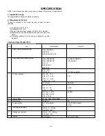
Page 6: ...fication TV 1 2 3 4 5 6 7 8 9 Video input applicable system Receivable broadcasting system RF input channel Input voltage Picture size Tuning system Operting environment Storage environment Display 1 PAL D K B G I 2 NTSC M 3 SECAM NTSC 4 43 1 PAL SECAM BG 2 PAL SECAM DK 3 PAL I I 4 SECAM L L 5 NTSC M 6 PAL N M 7 NTSC M VHF E2 E12 UHF E21 E69 CATV S1 S20 HYPER S21 S41 L L B C D VHF 2 13 UHF 14 69 C...

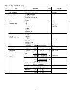
Page 7: ...Line2 Ready 12 SWITCH GND 14 SWITCH 1280 horiz By 768 vert pixels RGB strip arrangement Hard coating 3H Anti glare treatment of the front polarizer Item Specification Remark Unit No DVI I input Middle east NTSC Only Japan only LED Red dimmed Red Red dimmed H x V x D H V Sync ON ON OFF ON ON OFF Video Active OFF OFF LPL AUO CMO LPL AUO CMO Power consumption Max 170 3 0 typ 30 W W W W mm mm Type Siz...

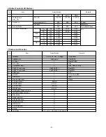
Page 8: ...T 1 Full SCART 1 1 1 1 1 BG DK BG I LL BG DK BG I LL X X O X O O X X X Pr vol ok menu tv av power Item Specification Remark No Top option PAL NTSC Rear RT RM Side Side Rear RT RM Rear RZ Rear RZ DVI D Sub 9 pin RM RM Stereo 6 Optical Feature LCD Module Item Remark Specification Viewing Angle CR 10 Luminance Contrast Ratio CIE Color Coordinates Typical MAX MIN ALL white All back LPL R L U D Luminan...

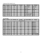
Page 9: ...z ATSC HDTV 1080i 59 94Hz 8 Component Video Input Y PB PR 9 PC Input Mode NO 1 2 3 4 5 6 7 8 9 10 11 12 13 Resoluton 640 x 480 640 x 480 640 x 480 800 x 600 800 x 600 800 x 600 800 x 600 1024 x 768 1024 x 768 1024 x 768 1280 x 768 1280 x 768 1920 x 1080 H freq kHz 31 469 35 37 500 35 156 37 879 48 077 46 875 48 363 56 476 60 023 47 693 45 00 33 75 V freq Hz 59 94 67 75 00 56 25 60 31 72 18 75 00 6...

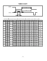
Page 10: ... 64 V 72 188 666 600 37 6 23 H 46 875 1056 800 16 80 160 V 75 0 625 600 1 3 21 H 48 363 1344 1024 24 136 160 V 60 004 806 768 3 6 29 H 56 476 1328 1024 24 136 144 V 70 069 806 768 3 6 29 H 60 023 1312 1024 16 96 176 V 75 029 800 768 1 3 28 H 47 776 1664 1280 64 128 192 V 59 870 798 768 3 7 20 Mode H V Sort 1 2 3 4 5 6 7 8 9 10 11 25 175 30 240 31 5 36 40 0 50 0 49 5 65 0 75 78 75 79 50 640x480 640...

Page 11: ...ontents Protection Set 2 3 1 HDCP DVI Digital Visual Interface is the link which transmits HD video of HD and STB when in sleep mode This function prevents the hazard of hang display thus securing the security against the contents and copy protection 2 3 2 To store in EEPROM AT24C16 in HDCP function connect DVI cable Detailed work content from work map reference Note HDCP will temporarily exclude ...

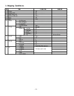
Page 12: ...rogram Manual Program Program Edit Favorite Program PSM SSM AVL Balance Input Child Lock Auto sleep Language H Position V Position Clock Phase Auto Configure Dynamic Contrast Brightness Colour Sharpness Tint Off 30 TV Pr 01 Off 16 9 None Dynamic 80 40 70 70 0 Flat Off 0 TV Off Off English Area Management Variable by each mode NTSC OPTION 3 Shipping Conditions ...

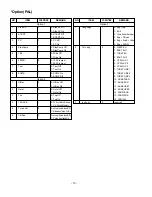
Page 13: ...n 0 Hotel Off 1 Hotel On 0 Top Off 1 Top On 0 Ch Sound Non Memory 1 Ch Sound Memory 0 except below area Off 1 Middle east Area Vol On 0 except below area Off 1 China Australia On Option 1 Option 2 NO ITEM CONDITION REMARK 1 2 3 Language Txt Lang Inch opt 1 0 0 0 Eng Only 1 EU5 2 12 nations Europe 3 Eng Chines 4 Eng Arab Urdu 5 Eng FARSI 0 WEST EU 1 EAST EU 1 2 TURKY EU 3 EAST EU 2 4 CYRILLIC 1 5 C...

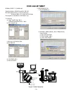
Page 14: ...14 13 25 6 5V 5V 5V 4 7K 4 7K 4 7K 74LS06 74LS06 OFF ON OFF ON 11 Figure 1 Cable Connection Windows EDID V1 0 User Manual Operating System MS Windows 98 2000 XP Port Setup Windows 98 Don t need setup Windows 2000 XP Need to Port Setup This program is available to LCD Monitor only 1 Port Setup a Copy UserPort sys file to c WINNT system32 drivers folder b Run Userport exe c Remove all default number...

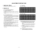
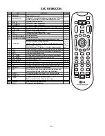
Page 15: ...automatic Afteradjustingthescreen W Badjustment Exittwotimes Adjustmentcompleted To enter into the adjustment mode To adjust horizontal line and sub brightness To select the multiple sound mode Mono Stereo or Foreign language To release the adjustment mode To easily adjust the screen according to surrounding brightness To easily adjust sound according to the program type To check component input T...

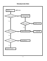
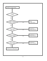
Page 16: ...ange Power B D Change IC1300 IC4 or IC8 Change LED Assy Change L808 L809 F801 F802 Check 24V or 12V of Power B D Check Output of IC1300 IC4 or IC8 Check LED Assy Check P101 Connector Fail Fail Fail Change L3 L1300 Check Output of L3 L1300 Fail Pass Fail Pass Pass Pass A Process ...

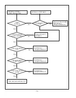
Page 17: ...Check inverter Connector or inverter Check input source cable and jack Repeat A PROCESS Fail Change L900 L901 L902 L903 Fail Change IC901 Fail Change inverter connector or inverter Fail Change panel link cable or module Fail Change module Fail Check panel link Cable or module Pass Pass Pass Pass B Process ...

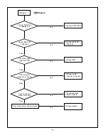
Page 18: ...A Process Check the input output of IC1 Check the input output of IC901 Check input source cable and jack Fail Re soldering or Change the defect part Fail Re soldering or Change the defect part Fail Pass Pass Pass Check the input output of IC500 IC600 Re soldering or Change the defect part Fail Pass ...

Page 19: ...of TU1000 Check the input output of IC1 Check the input output of IC500 IC600 Check input source cable and jack Fail Fail Fail Fail Re soldering or Change the defect part Fail Fail Re soldering or Change the defect part Check 5V 33V of TU1000 Re soldering or Change the defect part Pass Pass Pass Check the input output of IC901 Re soldering or Change the defect part Pass Pass ...

Page 20: ...e input Check the input source Fail Pass Re soldering or Change the defect part Check the input output of IC1 Fail Pass Re soldering or Change the defect part Check the input output of IC100 IC101 Fail Pass Change speaker Check the speaker Fail Pass ...

Page 21: ... MST9883 ADC FLI2300 RAM SM5301 GM5221 SCALER ROM LVDS or TTL OUT DVI R G B 3 3 R G B 8 8 8 PC_R G B 3 PC_R G B DVI 8 3 R G B HD_Y Pb Pr NT HD_Y Pb Pr 3 R L SIDE_COMP SIDE_Y C HD_COMP _ L R CVBS_L R PC_ LR LA7222C SIDE_ LR 3 R G B R G B CVBS_IN NTSC _ IF ...

Page 22: ...o the LCD module VCTI is the main microcomputer that processes both video signals and sound signals It also processes the RF signal received from the tuner The scaler enables to adjust timing on the LCD panel as well as an adjustment of the size and position of the input signal The graphic controller unit receives the PC analog RGB input and the DVI D digital signal and sends the PC input to the s...

Page 23: ...P750 P202 14Pin 12Pin 12Pin 12Pin 10Pin 6Pin 5Pin 3Pin P105 4 8 3 9 6 5 2 7 1 MAIN BOARD POWER BOARD WIRING DIAGRAM No Part No 1 2 3 4 5 6 7 8 9 Wiring Part List 6631T11020C 6631T20032E 6631T20032F 6631T25019K 6631T20033F 6631T20033C 6631T20033A 6631T20033E 6631T20033D ...

Page 24: ... 24 EXPLODED VIEW 010 050 070 080 090 020 100 060 110 120 130 140 150 030 160 040 ...

Page 25: ...UB TOTAL BRAND KEY BOARD 6871TST765A PWB PCB ASSEMBLY SUB 30LZ50 LED P SW TOTAL BRAND 6871TST762A PWB PCB ASSEMBLY SUB 26 27LZ50 LED P SW TOTAL BRAND 6871TST588A PWB PCB ASSEMBLY SUB 30LZ50 IR SUB TOTAL BRAND IR BOARD 6871TVT370B PWB PCB ASSEMBLY VIDEO RM 32 26 23LZ50 SIDE A V SUB TOTAL BRAND 6871TVT370A PWB PCB ASSEMBLY VIDEO RZ 30LZ50 SIDE A V SUB TOTAL BRAND 4951TKS157C METAL ASSEMBLY FRAME RZ ...

Page 26: ...L3 TR 50V 0 C1001 0CH3103K516 10000PF 50V 10 B Y5P 2012 R C1002 0CH3103K516 10000PF 50V 10 B Y5P 2012 R C1003 0CH3103K516 10000PF 50V 10 B Y5P 2012 R C1004 0CH3103K516 10000PF 50V 10 B Y5P 2012 R C1007 0CH3103K516 10000PF 50V 10 B Y5P 2012 R C1010 0CK273DK51A 27000PF 2012 50V 10 B Y5P R C107 0CK225DFK4A 2 2UF 2012 16V 20 20 F Y5V C109 0CH3103K516 10000PF 50V 10 B Y5P 2012 R C11 0CH3104K566 0 1UF 5...

Page 27: ...UF 50V 10 X7R 2012 R TP C639 0CH3104K566 0 1UF 50V 10 X7R 2012 R TP C64 0CH3104K566 0 1UF 50V 10 X7R 2012 R TP DATE 2004 8 31 S AL LOC NO PART NO DESCRIPTION SPECIFICATION C640 0CH3104K566 0 1UF 50V 10 X7R 2012 R TP C65 0CH3104K566 0 1UF 50V 10 X7R 2012 R TP C66 0CK106EF56A 10UF 3216 16V 10 X7R R TP C67 0CH3104K566 0 1UF 50V 10 X7R 2012 R TP C700 0CH3104K566 0 1UF 50V 10 X7R 2012 R TP C704 0CH3104...

Page 28: ...F56A 10UF 3216 16V 10 X7R R TP C73 0CK106EF56A 10UF 3216 16V 10 X7R R TP C750 0CK104CK56A 0 1UF 1608 50V 10 R TP X7R DATE 2004 8 31 S AL LOC NO PART NO DESCRIPTION SPECIFICATION C752 0CK104CK56A 0 1UF 1608 50V 10 R TP X7R C753 0CK104CK56A 0 1UF 1608 50V 10 R TP X7R C759 0CK104CK56A 0 1UF 1608 50V 10 R TP X7R C78 0CK106EF56A 10UF 3216 16V 10 X7R R TP C8 0CK104CK56A 0 1UF 1608 50V 10 R TP X7R C800 0...

Page 29: ...D NON 40V DATE 2004 8 31 S AL LOC NO PART NO DESCRIPTION SPECIFICATION ZD1301 0DR340009AA MBRS340 TP FAIRCHILD NON 40V D107 0DS226009AA KDS226 TP KEC SOT 23 80V 300 D711 0DD184009AA KDS184 TP KEC 85V 300 D102 0DS181009AA KDS181 TP KEC SOT 23 80V 30 D103 0DS181009AA KDS181 TP KEC SOT 23 80V 30 D104 0DZ620009HB UDZ S 6 2B TP ROHM SOD323 200 D105 0DZ620009HB UDZ S 6 2B TP ROHM SOD323 200 D703 0DZ5100...

Page 30: ... 0LC1032101A 10UH 10 3216 R TC FI C3216 1 L14 0LC1032101A 10UH 10 3216 R TC FI C3216 1 L15 0LC1032101A 10UH 10 3216 R TC FI C3216 1 L17 0LC1032101A 10UH 10 3216 R TC FI C3216 1 L2 0LC1032101A 10UH 10 3216 R TC FI C3216 1 L402 0LC1532101A 15UH 10 3216 R TC FI C3216 1 DATE 2004 8 31 S AL LOC NO PART NO DESCRIPTION SPECIFICATION L403 0LC1532101A 15UH 10 3216 R TC FI C3216 1 L7 0LC1032101A 10UH 10 321...

Page 31: ...T NO DESCRIPTION SPECIFICATION R725 0RH1000D622 100 1 10W 5 D R TP R729 0RH1000D622 100 1 10W 5 D R TP R730 0RH1000D622 100 1 10W 5 D R TP R737 0RH4701D622 4 7K 1 10W 5 D R TP R738 0RH4701D622 4 7K 1 10W 5 D R TP R755 0RH0102D622 10 1 10W 5 D R TP R756 0RH0102D622 10 1 10W 5 D R TP R802 0RH8200D622 820 1 10W 5 D R TP R805 0RH0752D622 75 1 10W 5 D R TP R806 0RH4700D622 470 1 10W 5 D R TP R809 0RH01...

Page 32: ...0RJ1000D677 100 OHM 1 10 W 5 1608 R TP R120 0RJ1000D677 100 OHM 1 10 W 5 1608 R TP DATE 2004 8 31 S AL LOC NO PART NO DESCRIPTION SPECIFICATION R121 0RJ0000D677 0 OHM 1 10 W 5 1608 R TP R122 0RJ1000D677 100 OHM 1 10 W 5 1608 R TP R123 0RJ2202D677 22K OHM 1 10 W 5 1608 R TP R124 0RJ1500D677 150 OHM 1 10 W 5 1608 R TP R125 0RJ4701D677 4 7K OHM 1 10 W 5 1608 R TP R127 0RJ3301D677 3 3K OHM 1 10 W 5 16...

Page 33: ... 5 1608 R TP R606 0RJ1000D677 100 OHM 1 10 W 5 1608 R TP R608 0RJ1000D677 100 OHM 1 10 W 5 1608 R TP DATE 2004 8 31 S AL LOC NO PART NO DESCRIPTION SPECIFICATION R609 0RJ1000D677 100 OHM 1 10 W 5 1608 R TP R62 0RJ1000D677 100 OHM 1 10 W 5 1608 R TP R64 0RJ1000D677 100 OHM 1 10 W 5 1608 R TP R66 0RJ1000D677 100 OHM 1 10 W 5 1608 R TP R68 0RJ1000D677 100 OHM 1 10 W 5 1608 R TP R70 0RJ1000D677 100 OH...

Page 34: ...0F409 430 OHM 1 6 W 1 00 TA52 R1704 0RN3300F409 330 1 6W 1 TA52 R1705 0RN2700F409 270 1 6W 1 TA52 R1706 0RN2701F409 2 7K OHM 1 6 W 1 00 TA52 SW1700 140 313A TACT 2LEAD 100G TA LG C D NO SW1701 140 313A TACT 2LEAD 100G TA LG C D NO SW1702 140 313A TACT 2LEAD 100G TA LG C D NO SW1703 140 313A TACT 2LEAD 100G TA LG C D NO DATE 2004 8 31 S AL LOC NO PART NO DESCRIPTION SPECIFICATION SW1704 140 313A TA...

Page 35: ...Date 2004 05 07 P No 3854TP3001A ...

Page 36: ...Date 2004 05 07 P No 3854TP3001A ...

Page 37: ...Aug 2004 Printed in Korea P NO 3828TSL104Y ...

Reviews: