- 14 -
ADJUSTMENT INSTRUCTIONS
8. Brightness Adjustment of Main/Sub
Screen
(1) Receive signal(RF 06Ch.) on the Main/Sub screen in the twin
picture.
(2) Confirms picture probably is the normal.
(3) Check the “US06CH” with naked eyes in 06Ch. pattern and if
there is difference, make the adjustment so that the field and
the letters are distinguished.
(4) Adjusting Main screen
1) Select the 6. CONTRAST by pressing “ADJ” key on the
remote control for adjustment.
2) Select the Contrast(m) of adjustment item using CH +/- key
and revises using VOL +/- key.
(5) Adjusting Sub screen
1) Select the 6. CONTRAST by pressing “ADJ” key on the
remote control for adjustment.
2) Select the Contrast(s) of adjustment item using CH +/- key
and revises using VOL +/- key.
* Only make adjus/- 2 at one time.
9. Check and adjustment RGB Alignment
9-1. Required Test Equipment
Remote control for adjustment
9-2. Preparation for Adjustment
(1) Connect power source with TV Set and turn TV Set on.
(2) Before adjusting, Heat Run more than 15 minutes.
9-3. Check and adjustment RGB Alignment
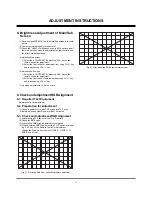
(1) After pressing EYE key, enter the (Fig. 3) pattern.
(2) Check the RGB Align
(3) When fitting RGB Align, adjustment is completed.
(4) When deviating RGB Align, select the 7. H-Position by press-
ing “ADJ” key on the Remote Control for Adjustment.
Change the Channel key to select H POS R, H POS G, H
POS B and fit color.
(Fig. 3) Deviating Red Pixel, collectively(before adjusting)
(Fig. 4) After adjusting RGB Align(normal screen)
Summary of Contents for RU-44SZ80L - - 44" Rear Projection TV
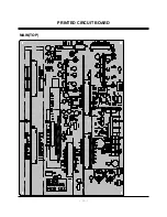
Page 15: ... 15 PRINTED CIRCUIT BOARD MAIN TOP ...
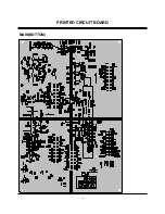
Page 16: ... 16 PRINTED CIRCUIT BOARD MAIN BOTTOM ...
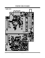
Page 17: ... 17 PRINTED CIRCUIT BOARD TUNER TOP ...
Page 18: ... 18 PRINTED CIRCUIT BOARD TUNER BOTTOM ...
Page 19: ... 19 PRINTED CIRCUIT BOARD DRIVER TOP ...
Page 20: ... 20 PRINTED CIRCUIT BOARD DRIVER BOTTOM ...
Page 21: ... 21 PRINTED CIRCUIT BOARD DIGITAL TOP ...
Page 22: ... 22 PRINTED CIRCUIT BOARD DIGITAL BOTTOM ...
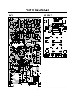
Page 23: ... 23 PRINTED CIRCUIT BOARD SMPS AC INPUT ...
Page 24: ... 24 PRINTED CIRCUIT BOARD SIDE A V CRM TOP CRM BOTTOM ...
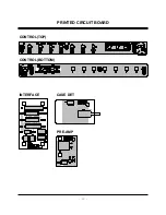
Page 25: ... 25 CASE DET PRE AMP INTERFACE CONTROL TOP CONTROL BOTTOM PRINTED CIRCUIT BOARD ...
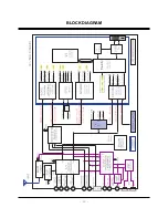
Page 26: ... 26 BLOCK DIAGRAM ...
Page 27: ... 27 NOTES ...
Page 40: ......
Page 41: ......
Page 42: ......
Page 43: ......


