- 6 -
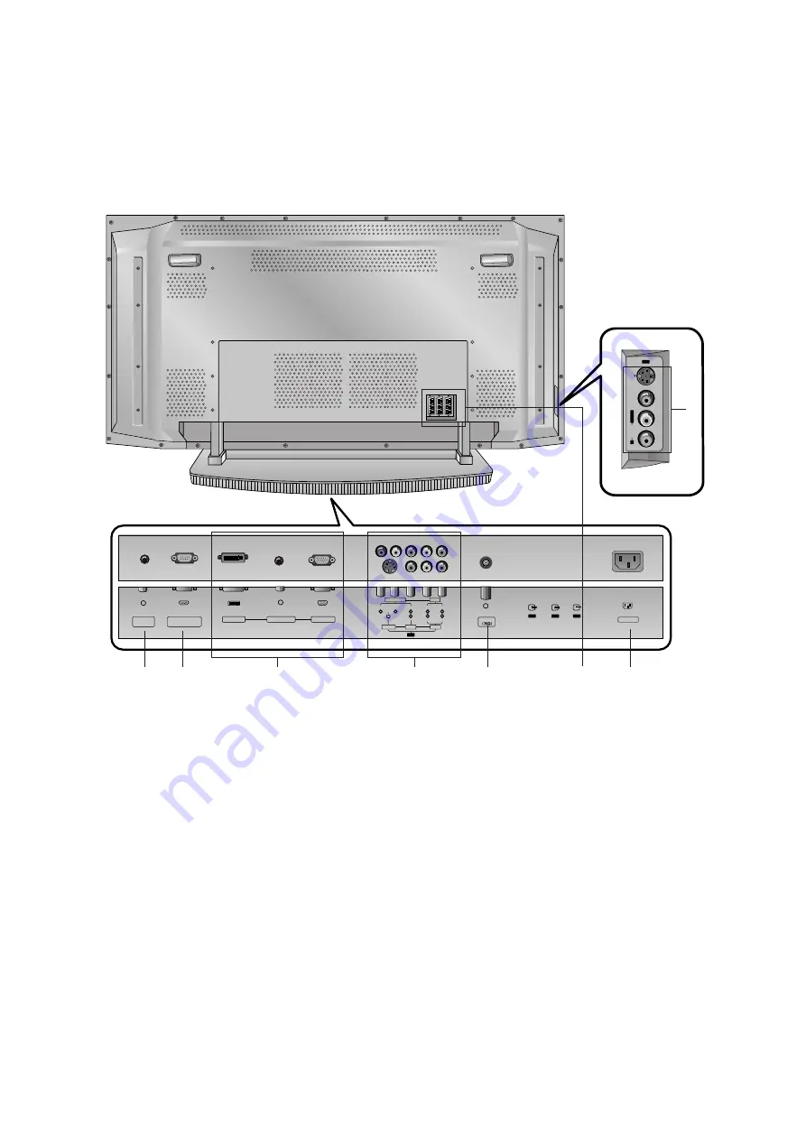
<Back Panel>
Antenna
REMOTE
CONTROL
S
-V
ID
E
O
V
ID
E
O
A
U
D
IO
RS-232C INPUT
DVI INPUT
(CONTROL/SERVICE)
AC INPUT
AUDIO INPUT
RGB INPUT
Y
P
B
P
R
L
R
L
(MONO)
R
COMPONENT
S-VIDEO
VIDEO
AUDIO
AUDIO
AV4
AV1
AV5
AV2
AV3
R
L/
M
O
N
O
1. REMOTE CONTROL
2. RS-232C INPUT(CONTROL/SERVICE) PORT
Connect to the RS-232C port on a PC.
3. DVI INPUT / AUDIO INPUT / RGB INPUT
Connect the monitor output socket of the PERSONAL COM-
PUTER to this socket.
4. COMPONENT INPUT
Connect DVD video outputs to Y, P
B
, P
R
of COMPONENT
INPUT and audio outputs to Audio sockets of AUDIO INPUT.
AUDIO/VIDEO IN SOCKETS (AV4)
Connect the audio/video out sockets of external equipment to
these sockets.
S-VIDEO/AUDIO IN SOCKETS
Connect the S-VIDEO out socket of an VCR to the S-VIDEO
socket.
Connect the audio out sockets of the VCR to the audio sock-
ets as in AV4.
5. ANTENNA INPUT
6. EURO SCART SOCKET
Connect the euro scart socket of the VCR to these sockets.
7. POWER CORD SOCKET
This Monitor operates on an AC power. The voltage is indi-
cated on the Specifications page. Never attempt to operate
the Monitor on DC power.
8. AUDIO/VIDEO IN SOCKETS (AV5)
S-VIDEO/AUDIO IN SOCKETS
3
4
5
6
8
7
1
2


