4-3
DECK MECHANISM DISASSEMBLY
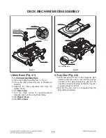
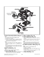
1. Main Base (Fig. 4-1)
1-1. Clamp Assembly Disc
1) Place the Clamp Assembly Disc as Fig. (A)
2) Lift up the Clamp Assembly Disc in direction of
arrow(A).
3) Separate the Clamp Assembly Disc from the
Holder Clamp.
1-1-1. Plate Clamp
1)
Turn the Plate Clamp to counterclockwise
direction and then lift up the Plate Clamp.
1-1-2. Magnet Clamp
1-1-3. Clamp Upper
2. Tray Disc (Fig. 4-2)
1) Insert and push a Driver in the emergency eject
hole(A) at the right side, or put the Driver on the
Lever(B) of the Gear Emergency and pull the
Lever(B) in direction of arrow so that the Tray Disc
is ejected about 15~20mm.
2) Pull the Tray Disc until it is separated from the
Base Main completely.
MAIN BASE
TRAY DISC
BASE MAIN
LEVER
BASE MAIN
BOTTOM SIDE VIEW
PLATE CLAMP
MAGNET CLAMP
CLAMP UPPER
HOLDER
BASE MAIN
Fig. 4-2
Fig. 4-1
(Fig. A)
DISC CLAMP ASSEMBLY
Summary of Contents for SH33SD-S
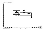
Page 25: ...2 16 4 SLED CONTROL RELATED SIGNAL NO DISC CONDITION FIG 4 1 1 2 3 4 1 2 3 4 ...
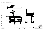
Page 27: ...2 18 FIG 7 2 DVD 7 DISC TYPE JUDGEMENT WAVEFORMS FIG 7 1 DVD 1 2 3 IC501 IC501 1 2 3 1 2 3 ...
Page 28: ...2 19 FIG 7 4 CD FIG 7 3 CD 1 2 3 IC501 IC501 1 2 3 1 2 3 ...
Page 29: ...2 20 FIG 8 2 CD 8 FOCUS ON WAVEFORMS FIG 8 1 DVD 1 2 3 1 2 3 4 4 1 2 4 3 IC501 ...
Page 41: ...2 32 2 IC401 MOTOR DRIVER PIN CONFIGURATION BLOCK DIAGRAM ...
Page 42: ...2 33 1 IC501 MPEG MT1389L PIN DESCRIPTION ...
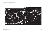
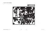
Page 66: ...2 69 2 70 PRINTED CIRCUIT BOARD DIAGRAMS 1 MAIN P C BOARD DIAGRAM TOP VIEW ...
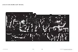
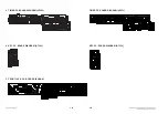
Page 67: ...2 71 2 72 MAIN P C BOARD DIAGRAM BOTTOM VIEW ...
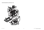
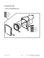
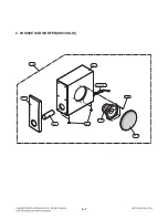
Page 74: ...2 PASSIVE SUBWOOFER SH33SD W 950 A90 951 953 956 954 952 955 WIRE90 3 7 ...
Page 75: ......

