background image

41

NO

YES

NO

YES


WARNING

 Before doing maintenance. Be sure to turn power and gas off, and do voltage discharge.

 Failure to follow these instructions can result in death or electric shock.

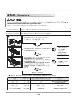
Trouble Symptom 

Measurement Condition 

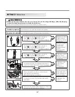
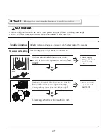
Abnormal vibration and noise are occurred in the back side of the machine.

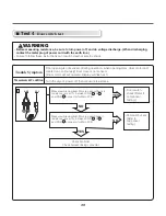
After turning power off, measure the resistance.

Is there abnormal vibration and noise 
at the drum motor operation step on Test 
mode?

Is there abnormal vibration and noise at the 
fan and the drum motor operation step, 
after pushing  start button additionally?

Check legs which is well installed or not.

•  

Check supply 
Voltage, the drum 
motor and the 
roller.

• 

 Check blower fan 
In the back side 
and clean it.

Drum motor

Roller

Blower fan

Test 6


Blower fan abnormal vibration & noise solution

Summary of Contents for TCD1870CGG

Page 1: ...imile or other electronic means publication modification copying or transmission of this Service Manual is STRICTLY PROHIBITED unless you have obtained the prior written consent of the LG Electronics entity from which you received this Service Manual The material covered by this prohibition includes without limitation any text graphics or logos in this Service Manual Copyright 2014 2017 LG Electro...

Page 2: ...S 43 17 DISASSEMBLY INSTRUCTIONS 47 18 EXPLODED VIEW 56 18 1 1 Control Panel Cabinet Cabinet Cover Assembly Single Card OPL Type 56 18 1 2 Control Panel Cabinet Cabinet Cover Assembly Single Coin Type 57 18 1 3 Control Panel Cabinet Cabinet Cover Assembly Stack Card OPL Type_Lower 58 18 1 4 Control Panel Cabinet Cabinet Cover Assembly Stack Card OPL Type_Upper 59 18 1 5 Control Panel Cabinet Cabin...

Page 3: ...un installateur ou un service d entretien qualifié ou par le fournisseur de gaz Caution Label all wires prior to disconnection when servicing controls Wiring errors can cause improper operation Note Purchaser shall post in a prominent location instructions to be Followed in the event the user smells gas The information to be posted shall be obtained by consulting with the local gas supplier Attent...

Page 4: ...dges only Observe above instructions when repackaging failed electronic control seembly in an anti static bag OR ESD problems are present everywhere ESD may damage or weaken the electronic control assembly The new control assembly may appear to work well after repair is finished but failure may occur at a later date due to ESD stress Touch your finger repeatedly to a green ground connection point ...

Page 5: ...5 ...

Page 6: ...6 ...

Page 7: ...7 ...

Page 8: ...8 ...

Page 9: ...9 Gw G G G G G Gz G Gj G G G G G G G G G G UG G G G U ...

Page 10: ...90mm D x 1022mm H 29in W x 4215 16in D x 401 4in H Stack dryer size 737mm W x 1090mm D x 2040mm H 29in W x 4215 16in D x 805 16in H Gas Dryer Max capacity IEC 9 0 cu ft 30lb Weight Side by side 220lbs 100kg Stackt 440lbs 200kg Specifications are subject to change by manufacturer Stack model is double Max capacity weight 2 SPECIFICATIONS ...

Page 11: ...stone ELECTRICITY CONSUMPTION Drum Motor 385W Stack is double BLDC Fan Motor 300W Stack is double Ignition controller 4VA Stack is double CONTROL TYPE Electric DRUM CAPACITY 13 6kg 30lb Stack is double GAS PRESSURE 5 0 10 5 w c 10 13 w c BURNER PRESSURE 3 8 w c 8 67 w c Natural Propane NOMINAL HEAT INPUT 55 000Btu hr Stack is double Product W x D x H Single 737mm x 1090mm x 1022mm Stack 737mm x 10...

Page 12: ...EATURES AND BENEFITS 1 DISPLAY LED 2 CYCLE BUTTON 3 START BUTTON 4 STATUS LED COIN OPL TYPE SIDE BY SIDE TCD1870CGS STACK TCD1870CGG UPPER LOWER 1 3 4 2 1 3 4 2 1 3 4 2 1 3 4 2 1 3 4 2 1 3 4 2 4 2 1 3 4 2 1 3 4 2 1 3 4 2 4 2 ...

Page 13: ... DISPLAY LED 2 CYCLE BUTTON 3 START BUTTON 4 STATUS LED COIN TYPE SIDE BY SIDE TCD1870QGS 1 3 1 3 4 2 1 3 4 2 1 3 4 2 1 3 1 3 4 2 1 3 4 2 1 3 4 2 1 3 4 2 1 3 4 2 1 3 4 2 1 3 4 2 STACK TCD1870QGG UPPER LOWER ...

Page 14: ...14 4 INITIAL STEPS FOR INSTALLING YOUR DRYER ...

Page 15: ...hyupunG G G G G G G G G G G G UG G G G G G G G G G G G y G G G G G G G G G G G G G G G G U t G G G G G G G G G G G G U Gh G G G G G G G G G UG n G G G G G G G G G G G G G G G G G G G G G G UG p G G G G G G G G G S G G G G G G G G G G G G G UG G G G G G G G U Leveling Feet w G G G G G G U Gw G G G G G G G G UG G z lwGYGLEVELING the Dryer ...

Page 16: ...16 z lwGZGProcedure for Reversing the Door Door and latch should be aligned at the center when closed Otherwise the door will not open lose or latch properly ...

Page 17: ...necting the Exhaust and Venting System The dryer must be installed wih a proper exhaust duct connection to the outside The dryer must be installed with provisions for adequate combustion and make up air supply 17 ...

Page 18: ...18 z lwG GConnection of Gas Supply z lwG GElectrical Plug Connection ...

Page 19: ...19 z lwG GPreparation of the Dryer z lwG GDryer Airflow z lwG_GConfirming Heat Source Operation ...

Page 20: ...20 LG T G G UzU G G GXWWWG U G G U XWL T G Gj G G G GYWWWT WWG U G G G G LG G G GXWWWG U Heating Value Btu ft3 LNG 1017 LPG 2573 High Altitude Burner Orifice Sizing ...

Page 21: ...achines Connect the lower coin harness to right coindrop Connect the upper coin harness to left coindrop 21 1 Coindrop Installation Install the coindrop to the control panel of upper dryer 5 DEBIT SYSTEM INSTALLATION INSTRUCTIONS ...

Page 22: ...22 Install the blue and white connector of the control panel to upper dryer Assemble the control panel of upper dryer Assemble the control panel of lower washer dryer ...

Page 23: ...ng plug to help guard against shock The plug should be plugged directed into a properly grounded suitably protected three prong receptacle This plug in order to be properly and fully effective must be plugged into a properly installed outlet that is grounded in accordance with all local codes and ordinances b The dryer when installed must be electrically grounded in accordance with local codes or ...

Page 24: ...0 feet 6 1 m It is also important that you use pipe joint compound that is insoluble in gas 6 A minimum 1 8 in NPT plugged tapping accessible for test gage connection must be installed immediately upstream of the gas supply connections to the dryer 7 To reduce the danger of gas leaks explosion and fire please follow and observe the following instructions and WARNINGS The dryer and its manually ope...

Page 25: ...bstances fan can cause noise bad drying performance and increase drying time 3 The lint screen if so equipped must be cleaned in accordance with the manufacturer s recommended frequency guidelines 4 Periodic examination of exhaust systems must be conducted in accordance with the manufacturer s recommended frequency for cleaning the exhaust system 5 Keep dryer area clear and free from combustible m...

Page 26: ... smooth on the inside low air resistance The exhaust duct must have gentle bends It applies to the installation of several dryers on a shared exhaust duct that The exhaust duct diameter must increase after each dryer EXHAUST DUCT ...

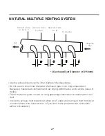
Page 27: ...and it will be cause of trouble Follow the below guide in case of using gathering exhaust duct installed with over 2 duct Incline the exhaust duct toward exit about an 45 angle when exhaust duct from dryer is connected to main exhaust duct If you don t make perpendicular connection airflow is disturbed Over sum of area A B C D Exit Inspection Cap Over sum of area A B C Over sum of area A B Over ar...

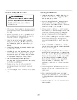
Page 28: ...nd roll any lint off the screen with your fingers Do not rinse or wash screen to remove lint Push the lint screen firmly back into place 3 Always ensure the lint screen is firmly secured before running the dryer Running the dryer with a loose lint screen may cause overheating and damage to the dryer and articles being dried 4 Some articles of clothing may shed more lint than Others towels for exam...

Page 29: ...e Dry More Dry Saturation Saturation Saturation 5 min per 5 min per 5 min per 2 min 2 min 2 min 68 4 C 60 4 C 47 3 C 47 5 C 47 5 C 38 5 C Time Dry LOAD Default Drying Electro sensor Temp Control Default time Temp Control Cooling Conditions of operation and termination Temp erature Dry Level Display time Temperature Control for each cycle ...

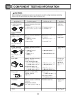
Page 30: ...the See Page 31 following terminal COM NC 1 lever open Resistance value 1 2 Lever push close Resistance value 4 Door switch following terminal 1 Door switch knob open Terminal COM NC 1 3 Terminal COM NO 1 2 2 Door switch push push Terminal COM NC 1 3 Terminal COM NO 1 2 Resistance value 1 Resistance value Resistance value Resistance value 1 If the knob is pressed the state is the opposite of what ...

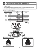
Page 31: ...31 11 MOTOR DIAGRAM AND SCHEMATIC ...

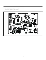
Page 32: ...12 CONTROL LAY OUT 32 PWB ASSEMBLY DISPLAY LAY OUT PWB ASSEMBLY LAY OUT ...

Page 33: ...33 PWB ASSEBMBLY SUB LAY OUT ...

Page 34: ...OR THER THERMOSTAT SAFETY THER Max 150 HI LIMIT THER Max 150 BLOWER THER Max 150 Ha Hb GND MOISTURE SENSOR DRUM MOTOR FAN MOTOR IGNITION CONTROLLER 0 0 0 0 0 0 0 0 0 0 0 0 0 1 5 1 6 25 6 97 5 6 97 5 6 6 5 25 MAIN PWB SUB PWB 1 1 NC NO NC NO NC NO NC NO NC NO 1 Caution Label all wires prior to disconnection when servicing controls Wiring errors can cause improper and dangerous operation Verify prop...

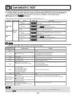
Page 35: ...at attached to the heater therefore do not activate it manually Do not press the door switch to operate the heater while the door is open This program has been added for testing the dryer and detecting errors During LqC1 test if no buttons are pressed for 4 minutes machine will be turned off automatically Do not use Note Diagnostic test display 1 Pressing the START button cycles to the next test f...

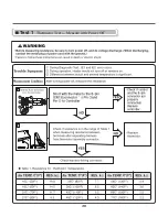
Page 36: ...36 Test 1 Thermistor Test Measure with Power Off ...

Page 37: ...ver is normal Is resistance below 1 between idler switch terminals Check motor Refer to Motor Diagram and Check Check if control connector is contacted Replace control Relay check Check controller connector Replace control Relay check Check controller connector Replace outlet Thermostat Refer to component Check idler assembly Drum belt cuts off Drum belt takes off from motor pulley Replace idler s...

Page 38: ...38 Test 3 Moisture Sensor WARNING ...

Page 39: ...motor and Heater run continuously Door close is not sensed Drum motor will not operate Display will flash at 1 Turn the dryer s power off then measure resistance NO YES NO YES Measure while door lint filter are closed Check it resistance is over 1 between CN3 or and CN5 connector for Main PCB Check hontroller Check harness linking connector Door switch check Refer to component testing Door switch ...

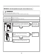
Page 40: ...during operation Check after power on Push rest switch 2 3 times and operate the machine Check ignition operation and spark is occurred or not Push the micro switch in the air flow switch And check spark is occurred dor not Check the ignition controller and main PCB Check the gas supply condition and the gas valve Check the air flow switch Reset switch Reset switch Test 5 Test when Ignition is not...

Page 41: ...the machine After turning power off measure the resistance Is there abnormal vibration and noise at the drum motor operation step on Test mode Is there abnormal vibration and noise at the fan and the drum motor operation step after pushing start button additionally Check legs which is well installed or not Check supply Voltage the drum motor and the roller Check blower fan In the back side and cle...

Page 42: ... The air flow switch is closed on normal close condition 2 The micro switch in the air flow switch is malfunction 3 The drum motor is malfunction 4 The drum belt or the drum motor harness is malfunction එO Y P එO P Check the duct blocked and fire occurred 1 Check the blower motor harness 2 Check the blower motor 1 Check the gas supply condition 2 Check the earth connection 3 Check the Air flow pat...

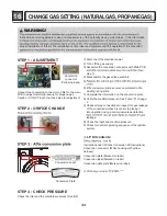
Page 43: ...wer Turn off the gas supply Assemble the conversion connector with Main PCB step 1 Disassemble the gas valve assembly existing rating plate Complete the information on the conversion plate Verify the manifold pressure See Table A on page 2 Check all pipe connections to inspect for gas leakage of the converted clothes dryer prior to placing it into operation using a noncorrosive leak detection leak...

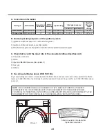
Page 44: ...Conversion connector Input and Manifold pressure See picture 2 Gas type Altitude D De rating at altitudes above 2000 ft 610m Dryer input ratings are based on measurements of altitude above sea level and need not be adjusted for altitude levels up to 2000 ft 610m Input ratings should be reduced at the rate of 4 percent for each 1000 ft 305m above sea level NOTE THE CONVERSION SHALL BE CARRIED OUT B...

Page 45: ...tting nut Yellow nut clock wise to the rated using a spanner on max heating operation Do not adjust the minimum pressure setting nut Black nut After adjusting the nut The manifold gas pressure doesn t satisfy and lower than rated manifold pressure additional setting way help you reach rated pressure refer to It can be adjusted additionally using the set up menu StUP 3ndt Natural gas pressure value...

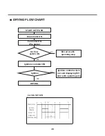
Page 46: ...um motor ON Fan motor ON Pre purge Ignition controller ON Air flow switch ON Ignition E24 error with operating stop Ignition controller lock out and displaying E21 error with operating stop NO NO YES YES Thermostat Ignition Spark Valve1 2 Flame rod Flame sense ...

Reviews: