15
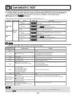
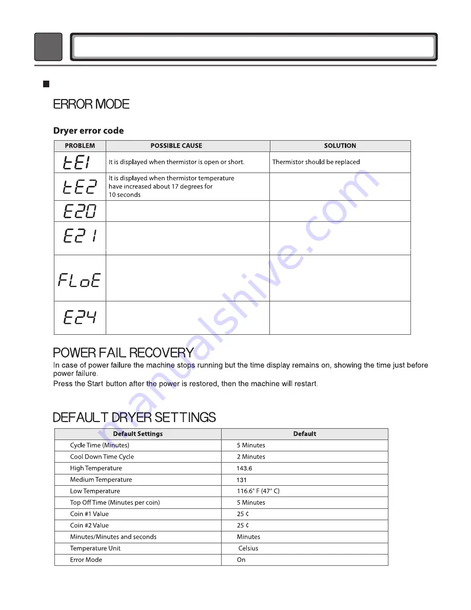
ERROR MODE
42
Meaning of Error Codes that LED displays during occurrence or problem.
1. Blower motor harness is disconnected
2. Blower motor coil or hall sensor is damaged
1. Gas supply is not good.
2. Earth connection is not good
3. Air flow path is not good
4. An ignition controller or a gas valve is malfunction.
The air flow switch is not closed on operating.
1. Lint is over stacked on the lint filter.
2. The air flow path is block in the machine.
3. The duct is blocked
4. The blower fan is stacked with lint or etc.
5. The air flow switch or harness is malfunction.
1. The air flow switch is closed on normal close condition.
2. The micro switch in the air flow switch is malfunction.
3. The drum motor is malfunction
4. The drum belt or the drum motor harness is malfunction
එO]YP
එO\\P
Check the duct blocked and fire occurred
1. Check the blower motor harness.
2. Check the blower motor.
1. Check the gas supply condition.
2. Check the earth connection
3. Check the Air flow path is block or not.
4. Check the ignition controller or the gas valve.
1. Clean the lint filter
2. Check the inside of the machine
3. Check the duct condition.
4. Check and clean the blower fan
5. Check the air flow switch and harness.
1. Check the air flow switch and replace.
2. Check the micro switch and replace.
3. Check the drum motor and replace.
4. Check both and replace.
Summary of Contents for TCD1870CGG
Page 5: ...5 ...
Page 6: ...6 ...
Page 7: ...7 ...
Page 8: ...8 ...
Page 9: ...9 Gw G G G G G Gz G Gj G G G G G G G G G G UG G G G U ...
Page 14: ...14 4 INITIAL STEPS FOR INSTALLING YOUR DRYER ...
Page 18: ...18 z lwG GConnection of Gas Supply z lwG GElectrical Plug Connection ...
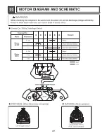
Page 31: ...31 11 MOTOR DIAGRAM AND SCHEMATIC ...
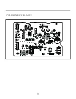
Page 32: ...12 CONTROL LAY OUT 32 PWB ASSEMBLY DISPLAY LAY OUT PWB ASSEMBLY LAY OUT ...
Page 33: ...33 PWB ASSEBMBLY SUB LAY OUT ...
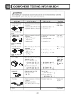
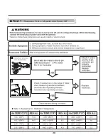
Page 36: ...36 Test 1 Thermistor Test Measure with Power Off ...

