3-9
SECTION3 ELECTRICAL
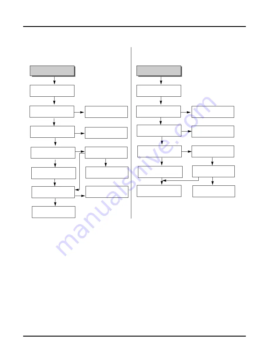
ELECTRICAL TROUBLESHOOTING GUIDE
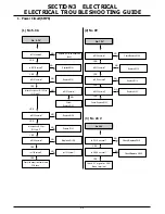
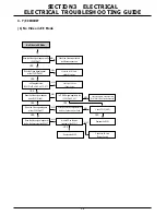
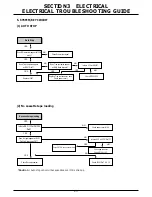
4. AUDIO CIRCUIT
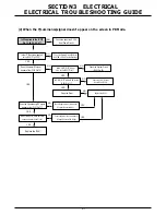
(1) No sound in EE Mode
Is the Audio signal applied to the
IC301 Pin 76?
NO
NO
Check the path of
LINE/AUDIO.
Check the IC501 Pin 2.
(Audio Mute "H".)
Check the IC501 Pin18(CLK),
17(Data) Line.
Does the CLK/Data signal(I
2
C)
appear at the IC301 Pin 23, 24?
No sound in EE Mode.
No sound.
YES
Is 5V applied to the IC301
Pin 75?
YES
Check the line of the 5V Line.
(Power Circuit)
YES
YES
Is the Audio Mute "High" signal applied
to the IC301 Pin 10?
Check the connection of the Audio
out Jack.
NO
NO
NO
YES
Does the Audio signal appear
at the IC301 Pin 96?
YES
Replace the IC301
YES
YES
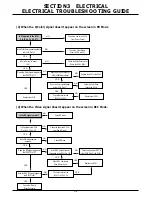
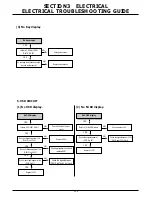
(2) No sound in PB MODE
Does the CLK/Data signal(I
2
C)
appear at the IC301 Pin 23, 24?
NO
NO
Check the IC501 Pin 18(CLK),
17(Data) Line.
Is the Audio Mute "H" applied to
the IC301 Pin 10?
No sound in PB Mode.
No sound.
YES
Is 5V applied to the
IC301 Pin 75?
YES
Check the line of the 5V Line.
(Power Circuit)
YES
NO
Check the connecting State between
the P3D02 Pin 6 and A/C Head.
Does the Audio signal appear
at the IC301 Pin 96?
NO
YES
Does the Audio signal appear
at the IC301 Pin 1?
YES
YES
NO
Replace the IC301
Check the IC501 Pin2.
YES
Summary of Contents for TL-AT130M
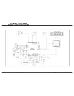
Page 23: ...3 14 3 13 SECTION3 ELECTRICAL BLOCK CIRCUIT DIAGRAMS 1 OVERALL WIRING DIAGRAM ...
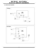
Page 24: ...3 16 3 15 SECTION3 ELECTRICAL BLOCK CIRCUIT DIAGRAMS 2 POWER BLOCK DIAGRAM ...
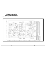
Page 25: ...3 18 3 17 SECTION3 ELECTRICAL BLOCK CIRCUIT DIAGRAMS 3 POWER CLRCUIT DIAGRAM ...
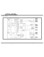
Page 26: ...3 19 SECTION3 ELECTRICAL BLOCK CIRCUIT DIAGRAMS 4 AUDIO BLOCK DIAGRAM ...
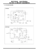
Page 27: ...3 20 SECTION3 ELECTRICAL BLOCK CIRCUIT DIAGRAMS 5 Y C BLOCK DIAGRAM ...
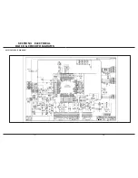
Page 28: ...3 22 3 21 SECTION3 ELECTRICAL BLOCK CIRCUIT DIAGRAMS 6 A V CIRCUIT DIAGRAM ...
Page 29: ...3 23 SECTION3 ELECTRICAL BLOCK CIRCUIT DIAGRAMS ...
Page 30: ...3 25 3 24 SECTION3 ELECTRICAL BLOCK CIRCUIT DIAGRAMS 7 SYSTEM BLOCK DIAGRAM ...
Page 31: ...3 26 SECTION3 ELECTRICAL BLOCK CIRCUIT DIAGRAMS ...
Page 32: ...3 28 3 27 SECTION3 ELECTRICAL BLOCK CIRCUIT DIAGRAMS 8 SYSTEM CLRCUIT DIAGRAM ...
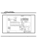
Page 33: ...3 30 3 29 SECTION3 ELECTRICAL BLOCK CIRCUIT DIAGRAMS 9 JACK CLRCUIT DIAGRAM ...
Page 34: ...3 32 3 31 SECTION3 ELECTRICAL BLOCK CIRCUIT DIAGRAMS 10 KEY BOARD CLRCUIT DIAGRAM ...
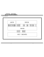
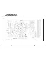
Page 35: ...3 34 3 33 SECTION3 ELECTRICAL PRINTED CIRCUIT DIAGRAMS 1 MAIN P C BOARD ...

