background image

MAINTENANCE/INSPECTION PROCEDURE

4-21

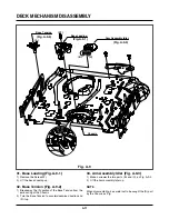
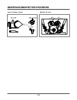
5-2) Greasing

(1) Greasing guidelines

Apply grease, with a cleaning patch. Do not use exces-
sive grease. It may come into contact with the tape
transport or drive system. Wipe excessive grease and
clean with cleaning patch wetted in Isopropyl Alcohol.

(2) Periodic greasing

Grease specified locations every 5,000 hours.

NOTE:Greasing Points

3

5

7

6

1

7

2

4

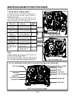
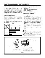
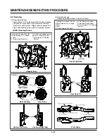
1) Loading Path Inside & Top side
2) Base Assembly P2, P3 stopper
3) Shaft
4) L/D Motor Gear Wheel Part

5) Arm Take-up Rubbing Sections
6)Reel S,T shaft(G381:Yellow)
7) Arm Assembly F/L Rotating

Sections

Guide Rail

Base Loading

Gear Drive

Gear Sector

Gear Cam

Gear Part

Chassis (Left Side)

Chassis (Right Side)

5

7

8

1

2

6

4

3

Slider Guide

Slider Guide

1) Loading Path Inside & Top side
2) Base Assembly P2,P3 stopper
3) Shaft
4) Shaft
5) Clutch Assembly D35 Shaft

6) Plate Slider Guide Sections
7) Plate Slider Guide Sections
8) Gear Assembly P2, P2 Rubbing

Sections

Chassis (Top)

Chassis (Bottom)

Gear Rack F/L

Plate Slider

Summary of Contents for TL-AT130M

Page 1: ...UNIT READ THE SAFETY PRECAUTIONS IN THIS MANUAL ALARM KEY LOCK PAUSE STILL POWER TIMER MENU REC REC PB SPEED TRACKING MOVE SEL DOWN UP REV REW F F CUE STOP EJECT PLAY REC CHK TIME LAPSE VCR SERVICE MANUAL APRIL 2006 Printed in Korea ...

Page 2: ...AUDIO CIRCUIT 3 9 5 SYSTEM KEY CIRCUIT 3 11 6 OSD CIRCUIT 3 12 BLOCK CIRCUIT DIAGRAMS 3 13 1 OVERALL WIRING DIAGRAM 3 13 2 POWER BLOCK DIAGRAM 3 15 3 POWER CIRCUIT DIAGRAM 3 17 4 AUDIO BLOCK DIAGRAM 3 19 5 Y C BLOCK DIAGRAM 3 20 6 A V CIRCUIT DIAGRAM 3 21 7 SYSTEM BLOCK DIAGRAM 3 24 8 SYSTEM CIRCUIT DIAGRAM 3 27 9 JACK CIRCUIT DIAGRAM 3 29 10 KEY BOARD CIRCUIT DIAGRAM 3 31 PRINTED CIRCUIT DIAGRAMS...

Page 3: ...6 hours NT T 120 PAL E 180 6H 18 hours NT T 120 PAL E 180 18H 30 hours NT T 120 PAL E 180 30H 72H 960H Tape Width 0 5 in 12 7 mm Rewind Time About 65 seconds NT T 120 PAL E 180 Video Signal System PAL CCIR Standard 625 lines 50 fields PAL type color signal Video Signal System NTSC EIA Standard 525 lines 60 fields NTSC type color signal Video Input 1 0 Vp p 75 ohms unbalanced Video Output 1 0 Vp p ...

Page 4: ... DOWN BUTTON 7 UP BUTTON 8 ALARM INDICATOR 9 KEY LOCK INDICATOR 10 CASSETTE LOADING SLOT 11 CLEAR KEY LOCK OFF BUZZER OFF 12 CLOCK COUNT REMAIN 13 SHUTTLE RING 14 JOG RING 15 PAUSE STILL BUTTON 16 PLAY REC CHECK BUTTON 17 STOP EJECT BUTTON FRONT REAR 1 POWER CORD 2 AUDIO IN OUT JACK 3 VIDEO IN OUT JACK 4 RESET BUTTON 5 12 PIN TERMINAL BLOCK ...

Page 5: ...CORD INDICATION 5 TIMER INDICATION 6 CASSETTE INDICATION 7 INDEX INDICATION 8 POWER FAILURE INDICATION 9 KEY LOCK INDICATION 10 REPEAT INDICATION 11 FUNCTION INDICATION 12 VCR FUNCTION INDICATION INDICATOR PANEL VCR FUNCTION INDICATION SECTION1 SUMMARY LOCATION OF CUSTOMER CONTROLS ...

Page 6: ...meras in general space with using camera multi plexer Outputs whether Alarm Recording is working The terminal that stops Alarm Record in Auto mode The input terminal to make Series Record work 1 ALARM IN 2 ALARM OUT 3 ALARM RESET 5 SERIES IN 6 SERIES OUT 7 WARNING OUT 8 TRIGGER OUT 10 LOW TAPE OUT 11 1 SHOT REC IN 4 9 12 GND VIH 4 5V VIL 0 0 6V T above 250 msec VIH 4 5V VIL 0 0 6V T ALARM REC STAT...

Page 7: ... in the left upper erases audio signal in dubbing Audio head in the right upper records and playes the audio signal CTL head in the right lower records and detects CTL pulse to control tape speed 8 Head F E Is abbreviation of Full Erased Head erases the signal recorded on a tape clearly and absorb vibration of tape 12 Arm Ass y Idler Is located between T UP reel and supply reel Transfers ratative ...

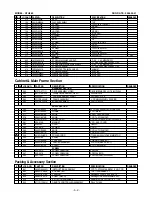
Page 8: ... S040F CASE LV TL1960 2960 MOLD AIRHALL BA 260 3210R 0023A FRAME VCR MAIN 277 4940R Z075A KNOB SHUTTLE TL AR30M 278 4940R Z076B KNOB CCD TL AT130 MOLD 280 3720R F721D PANEL VIDEO CCD LV TL1960 S MOLD HIPS 40AF 281 524 013A MAGNET VCR ASSY DOOR 283 3580R V090A DOOR CCD TIME LAPSE MOLD DOOR CST 284 442 681A SPRING DOOR 285 4940R Z086A KNOB CCD LV TL124 MOLD 286 4940R S017A KNOB SLIDE LV TL24 300 641...

Page 9: ...tion Parts list ASSEMBLY PARTS SECTION A42 6871RK5700K Ass y Front PCB SNILN4T3526 A43 05503805 ASS Y FRONT CAVINET NTH960 C TYPE A44 6871R 4462A Ass y Ant PCB TL AR30 SERIES A46 3501RK3200B Ass y Main PCB CCD LV TL1960 SECTION2 CABINET MAIN FRAME EXPLODED VIEWS ...

Page 10: ...NO DESCRIPTION SPECIFICATION REMARKS 801 3835RS0069N INSTRUCTION ASSEMBLY CCD TL AT330M AABBDL1_ENG_POR_ 802 3890R C065K BOX MASTER TL AT330M AABBDL 1 803 3920R E016A PACKING Packing LV TL24I 0 02 0 EPS 10 804 3858R S001A SHEET MECH Packing LDPE 600M 630MM 0 5 VC 808 534 008C BATTERY MANGANESE AAAM R03 SEOTONG 1 5 V 1PA 900 6711R1P041H REMOTE CONTROLLER P9 LV TL1960 ASSEMBLY MODEL TL AT130M Packin...

Page 11: ...l trigger signal to the specification 416 20 sec with changing VR501 WAVEFORM CONNECTION CHART OF MAIN PWB Fig 3 1 Connection chart of PG adjustment Caution Caution When repairing the power part just after pulling out the power code there is hazard of electical shock caused by the charged electricity at the peripheral circuit component primary power such as condenser C807 150µF So begin repairing ...

Page 12: ...D103 No 5 3V Is F101 normal Check Replace D109 No 12V Is D109 normal YES Is BD101 normal Replace D110 NO YES YES NO Replace Q170 NO Replace Q152 NO Check Replace Q163 YES YES YES Is Q159 normal Check H signal at Q161 Base terminal Check Replace D110 No 24V Is D110 normal NO Check Replace Q152 NO 3 No 24 V Is D109 normal YES NO NO Is L103 normal NO Replace IC103 Replace D109 Is L103 normal YES Is t...

Page 13: ...70 normal Is there about 13 5V at Q107 Base Check Replace D155 D156 D157 Replace D106 NO Replace Q153 Replace Q157 No 5 2V Is D106 normal Replace D109 No 10V Is D109 normal YES Is Q153 normal YES Check Replace Q156 YES NO Check Replace Q107 ZD103 NO SECTION3 ELECTRICAL ELECTRICAL TROUBLESHOOTING GUIDE ...

Page 14: ... Drum motor stops Check the Ass s between connector PMC01 and Drum motor YES NO NO Aren t pattern or componets between IC501 Pin34 and PMC01 Pin12 short NO Does Drum PWM pulse appear at IC501 Pin34 Does DFG pulse appear at IC501 Pin65 Does Drum PWM pulse appear at IC501 Pin34 When the drum moter stop Is there 12V at PMC01 Pin8 YES Is there 2 8V at PMC01 Pin12 YES NO Does DFG pulse appear at PMC01 ...

Page 15: ...ppear at PMC01 Pin1 Check the Ass y of Capstan motor When the capstan motor stops Is it 12VA at PMC01 Pin2 YES Is there 2 8V at PMC01 Pin9 YES NO Does PWM signal appear at IC501 Pin 33 NO NO Aren t pattern or componets between IC501 Pin67 and PMC01 Pin1 short Replace IC501 YES NO YES Check CFG signal appear at IC501 Pin67 Does Capstan PWM signal appear at IC501 Pin33 YES Aren t pattern or componet...

Page 16: ...the IC3G1 Pin9 YES Does the Video signal appear at the IC301 Pin38 YES Check the Video input Jack jack Board connection YES Is I 2 C BUS signal applied to the IC301 Pin 23 24 Check C316 AGC Replace the Q380 Check the System Circuit Refer to SYSTEM I 2 C BUS Trouble Shooting NO Does the Video signal appear at the IC501 Pin 47 YES Does the Video signal appear at the Emitter terminal of the Q380 YES ...

Page 17: ... 23 24 YES Does the normal RF signal appear at the IC301 Pin74 YES Check the System Circuit Refer to SYSTEM I 2 C BUS Trouble Shooting YES YES Replace the IC301 Replace the IC301 Does the Y Luminance RF signal appear at the IC301 Pin 17 YES Is the Y Luminance Video waveform showed up at the IC301 Pin 41 YES YES Check the System Circuit IC501 Pin 23 NO NO NO NO Is V H S W H about 3 4V at the IC301 ...

Page 18: ...eck the Q304 NO NO Check the line of the 5 3VA Line Power Circuit Replace the X301 or the X302 NO NO Does the X301 4 43MHz or X302 3 58MHz oscillate YES 4 When the Video signal doesn t appear on the screen in REC Mode Check the circuit of the IC301 Pin 90 92 94 NO NO Check PB Mode Is the EE signal normal Is 5V applied to the IC301 Pin 16 40 55 58 87 YES Does PB Mode operate normally YES Check the ...

Page 19: ...to the IC301 Pin 10 Check the connection of the Audio out Jack NO NO NO YES Does the Audio signal appear at the IC301 Pin 96 YES Replace the IC301 YES YES 2 No sound in PB MODE Does the CLK Data signal I 2 C appear at the IC301 Pin 23 24 NO NO Check the IC501 Pin 18 CLK 17 Data Line Is the Audio Mute H applied to the IC301 Pin 10 No sound in PB Mode No sound YES Is 5V applied to the IC301 Pin 75 Y...

Page 20: ...ed YES Is Playback O K YES Refer to No sound in PB Mode YES YES Does the Audio waveform appear at the IC301 Pin 7 NO NO Check the CLK Date line and replace the IC301 Check the Audio R P E connector and Head NO YES Check the IC501 Pin 96 Audio Mute H Is 3 0 4 5V applied to the Emitter of the Q481 YES NO NO NO Check the line of the 5V Power Circuit Does the Erase signal appear at the FL401 Pin 6 YES...

Page 21: ...1 NO Replace T up reel sensor of deck Check power circuit YES Check DP06 LP03 Replace IC501 NO YES 2 No cassette tape loading NO NO Is there 5 3V at IC501 Pin73 Check IC501 Pin7 8 9 10 No cassette tape loading Is there REG 12V at PMCQ1 Pin8 YES Does H signal appear at IC501 Pin62 while inserting CST Check power circuit L104 Check power circuit Check D106 L103 Check Deck mechanism NO NO YES YES Che...

Page 22: ...ircuity Does oscillation appear at the IC501 Pins 40 41 NO NO NO YES Does oscillation appear at the IC501 PIns 37 38 YES Check peripheral circuit and replace X501 YES No OSD display 6 OSD CIRCUIT 1 No OSD display Does Video signal appear at the IC501 Pin 47 YES NO Check the signal between IC501 Pin47 and V out Jack Replace IC501 YES Refer to 5 No OSD picture Check the signal between IC301 Pin 29 a...

Page 23: ...3 14 3 13 SECTION3 ELECTRICAL BLOCK CIRCUIT DIAGRAMS 1 OVERALL WIRING DIAGRAM ...

Page 24: ...3 16 3 15 SECTION3 ELECTRICAL BLOCK CIRCUIT DIAGRAMS 2 POWER BLOCK DIAGRAM ...

Page 25: ...3 18 3 17 SECTION3 ELECTRICAL BLOCK CIRCUIT DIAGRAMS 3 POWER CLRCUIT DIAGRAM ...

Page 26: ...3 19 SECTION3 ELECTRICAL BLOCK CIRCUIT DIAGRAMS 4 AUDIO BLOCK DIAGRAM ...

Page 27: ...3 20 SECTION3 ELECTRICAL BLOCK CIRCUIT DIAGRAMS 5 Y C BLOCK DIAGRAM ...

Page 28: ...3 22 3 21 SECTION3 ELECTRICAL BLOCK CIRCUIT DIAGRAMS 6 A V CIRCUIT DIAGRAM ...

Page 29: ...3 23 SECTION3 ELECTRICAL BLOCK CIRCUIT DIAGRAMS ...

Page 30: ...3 25 3 24 SECTION3 ELECTRICAL BLOCK CIRCUIT DIAGRAMS 7 SYSTEM BLOCK DIAGRAM ...

Page 31: ...3 26 SECTION3 ELECTRICAL BLOCK CIRCUIT DIAGRAMS ...

Page 32: ...3 28 3 27 SECTION3 ELECTRICAL BLOCK CIRCUIT DIAGRAMS 8 SYSTEM CLRCUIT DIAGRAM ...

Page 33: ...3 30 3 29 SECTION3 ELECTRICAL BLOCK CIRCUIT DIAGRAMS 9 JACK CLRCUIT DIAGRAM ...

Page 34: ...3 32 3 31 SECTION3 ELECTRICAL BLOCK CIRCUIT DIAGRAMS 10 KEY BOARD CLRCUIT DIAGRAM ...

Page 35: ...3 34 3 33 SECTION3 ELECTRICAL PRINTED CIRCUIT DIAGRAMS 1 MAIN P C BOARD ...

Page 36: ...3 35 SECTION3 ELECTRICAL PRINTED CIRCUIT DIAGRAMS PRINTED CIRCUIT BOARD DIAGRAMS 2 KEY 1 P C BOARD 3 KEY 2 P C BOARD 4 JACK P C BOARD ...
Page 37: ... Service 4 12 1 Mechanism Alignment Position Check 4 13 2 Preparation for Adjustment 4 14 3 Checking Torque 4 14 4 Guide Roller Height Adjustment 4 15 4 1 Preliminary Adjustment 4 15 4 2 Precise Adjustment 4 15 5 Audio Control A C Head Adjustment 4 16 5 1 Preliminary Adjustment 4 16 5 2 Confirmation of Tape Path between Pinch Roller and Take up Guide 4 17 5 3 Precise Adjustment Azimuth Adjustment ...

Page 38: ...ssembly P4 Chassis Embossing A 5 T 17 Opener Lid Chassis Embossing A 5 T 17 18 Arm Assembly Pinch Shaft A 5 T 17 19 Lever T Up Arm T Up 1 Hook A 5 T 17 18 20 Belt Capstan Motor Capstan 3 Screw A 6 B 21 Lever F R Locking Tab A 6 B 20 21 22 Clutch Assembly D35 Washer A 6 B 23 Brake Assembly Capstan Locking Tab A 6 B 24 Gear Drive Gear Cam Washer Hook A 7 B 25 Gear Sector 1 Hook A 7 B 20 21 23 26 Pla...

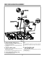
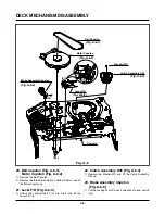
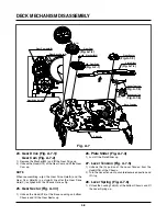
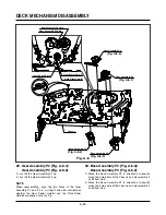
Page 39: ...e the Drum assembly 3 Unhook H1 H2 and separate the Holder FPC and Cap FPC 1 1 Drum Motor 1 Remove two Screws S2 and disassemble the Stator of the Drum Motor 2 Remove two Screws S3 and separate the Rotor of the Drum Motor from the Drum Sub assembly NOTE When reassembling confirm A portion of the Drum Sub assembly whether the Carbon Brush is in there or not Fig A 1 Fig B 1 Holder FPC Drum FPC Cap F...

Page 40: ...te Top Arm Assembly F L Spring Lever S W Gear Assembly Rack F L Chassis Opener Door Bracket Assembly L D Motor Holder Assembly CST B C D E H6 A B Lever Assembly S W H8 Fig A 2 Fig A 2 1 Fig A 2 2 Fig A 2 6 Fig A 2 7 Fig A 2 5 Fig A 2 3 Fig A 2 4 ...

Page 41: ...or Figure A 2 3 1 Turn the Opener Door clockwise and remove it through the guide hole of the Chassis 5 Bracket Assembly L D Motor Fig A 2 4 1 Unplug the Connector C1 2 Unhook three Hooks H3 H4 H5 on bottom side of the Chassis lift up the Bracket Assembly L M and disassem ble the Bracket Assembly L D Motor 6 Gear Assembly Rack F L Fig A 2 5 1 Move the Gear Assembly Rack F L in direction of arrow A ...

Page 42: ...e direction and lift it up 10 Head F E Fig A 3 2 1 Breakaway the A portion of the Head F E from the embossing of the Chassis turn it to counterclockwise direction and lift it up 11 Base Assembly A C Head Fig A 3 3 1 Remove the Screw S4 and lift the Base Assembly A C Head up A Arm Assembly Cleaner Base Assembly A C Head S4 Head F E A Chassis Fig A 3 Fig A 3 1 Fig A 3 3 Fig A 3 2 ...

Page 43: ... Brake Assembly RS Fig A 4 2 1 Unhook the Spring RS from the Hook H10 of the Chassis 2 Lift the Brake Assembly T up 14 Arm Assembly Tension Fig A 4 3 1 Unhook the Spring Tension from the Hook H11 of the Arm Assembly Tension 2 Unhook the Hook H12 of the Base Tension and lift the Arm Assembly Tension up NOTE Difference for Springs 15 Reel S Reel T Fig A 4 4 1 Difference for Reel S Reel T Spring TB S...

Page 44: ...ner Lid Fig A 5 2 1 Breakaway the B portion of the Opener Lid from the embossing of the Chassis 2 Turn the Opener Lid to clockwise direction and lift it up 18 Arm Assembly Pinch Fig A 5 3 1 Lift the Arm Assembly Pinch up NOTE When reassembling confirm the C portion of the Arm Assembly Pinch is inserted to the Chassis hole correctly as Fig 19 Lever T up Fig A 5 4 Arm T up Fig A 5 5 1 Unhook the Hoo...

Page 45: ...apstan 2 Remove the three Screws S5 on bottom Chassis and lift the Motor Capstan up 21 Lever F R Fig A 6 3 1 Unlock the Locking Tab L1 as Fig A 6 3 and lift the Lever F R up 22 Clutch Assembly D35 Fig A 6 4 1 Remove the Washer W1 and lift the Clutch Assembly D35 up 23 Brake Assembly Capstan Fig A 6 5 1 Pull the Locking Tab L2 back in direction of arrow and lift it up Fig A 6 1 Fig A 6 2 Fig A 6 3 ...

Page 46: ...and the Gear Cam Hole B in a straight line after the Gear Drive Hole C is aligned with the Chassis Hole as Fig 25 Gear Sector Fig A 7 3 1 Unhook the Hook H15 of the Base Loading on bottom Chassis and lift the Gear Sector up 26 Plate Slider Fig A 7 4 1 Just lift the Plate Slider up 27 Lever Tension Fig A 7 5 1 Unhook the A portion of the Lever Tension from the Hook H16 of the Chassis 2 Turn the Lev...

Page 47: ... P3 up NOTE When reassembling align the two holes of the Gear Assembly P2 and P3 in a straight line after confirmation whether the Gear Sector Hole A and the Plate Slider Hole B are aligned or not as Fig 30 Base Assembly P2 Fig A 8 3 Base Assembly P3 Fig A 8 4 1 Move the Base Assembly P2 in direction of arrow A along the guide hole of the Chassis and disassemble it on bottom side 2 Move the Base A...

Page 48: ...ion Fig A 9 2 1 Breakaway the A portion of the Base Tension from the embossing of the Chassis 2 Turn the Base Tension to counterclockwise direction and lift it up 33 Arm Assembly Idler Fig A 9 3 1 Make narrower the two parts B and C as Fig A 9 3 2 Lift the Arm assembly Idler up NOTE When disassembling be careful not to be caught the D part by the Chassis as Fig Fig A 9 1 Fig A 9 2 Fig A 9 3 ...

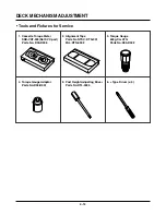
Page 49: ...00 D006 4 Torque Gauge Adaptor Parts No D09 R001 5 Post Height Adjusting Driver Parts No DTL 0005 6 Type Driver ø 5 2 Alignment Tape Parts No NTSC DTN 001 PAL DTN 0002 3 Torque Gauge 3 600g Cm ATG 3 Parts No D00 D002 SRK VIDEO CASSETTE TORQUE METER VHT 303 S R K V H T S SRK V HT T 300 250 200 150 50 0 300 250 200 150 50 0 100 ...

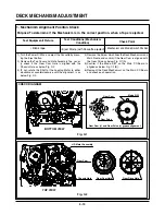
Page 50: ...is as below Fig C 2 4 Remove the Screw which fixes the Deck Mechanism and Main Frame and confirm if the Gear Cam is aligned with the Gear Drive as below Fig C 1 A 5 Confirm if the Mode S W on the Main P C Board is aligned as below Fig C 1 B 6 Remount the Deck Mechanism on the Main P C Board and check each operation Gear Cam Gear Drive A Mode S W B L D Motor Assembly Gear Cam Chassis Hole Gear Cam ...

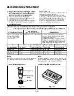
Page 51: ...the Torque Gauge affixed NOTE The torque reading to measure occurs when the tape abruptly changes direction from Fast Forward to Rewind Mode when quick braking is applied to both Reels SRK VIDEO CASSETTE TORQUE METER VHT 303 S R K V H T S SRK V HT T 300 250 200 150 50 0 300 250 200 150 50 0 100 Test Equipment Fixture Torque Gauge 600g cm ATG Torque Gauge Adaptor Cassette Torque Meter SRK VHT 303 C...

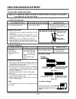
Page 52: ...velope CH 2 NTSC SW 30Hz PAL SW 25Hz Head Switching Output Point RF Envelope Output Point Test Conditions VCR VCP State Play an Alignment Tape Adjustment Point Guide Roller Height Adjustment Screws Fig C 4 2 Fig C 4 3 P3 POST ADJUSTMENT P2 POST ADJUSTMENT Turn the Roller Guide Height Adjustment Screw slightly to flatten the waveform Tracking Control at center RF ENVELOPE OUTPUT TEST POINT OSCILLOS...

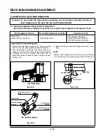
Page 53: ...Screw Fig C 5 3 A C Head Tape Tape 0 2 0 25mm P4 5 1 Preliminary Adjustment Height and Tilt Adjustment Perform the Preliminary Adjustment when there is no Audio Output Signal with the Alignment Tape 1 Initially adjust the Base Assembly A C Head as shown Fig C 5 1 by using the Height Adjustment Screw B 2 Play a blank tape and observe if the tape passes accu rately over the A C Head without tape cur...

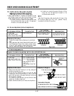
Page 54: ...ernately adjust the Azimuth Adjustment Screw A and the Tilt Adjustment Screw C for maximum output of the 1KHz and 7KHz segments while maintaining the flattest envelope differential between the two frequencies Adjustment Procedure 5 3 Precise Adjustment Azimuth adjustment 6 X Value Adjustment Fig C 5 4 1KHZ Oscilloscope Alignment Tape SP only Screw Driver Type 5mm CH 1 PB RF Envelope CH 2 NTSC SW 3...

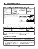
Page 55: ...sm Condition Play the Blank Tape Play an Alignment Tape Adjustment Points Guide Roller Precise Adjustment Switching Point Tracking Preset X Value Checking Adjustment Procedure Play a blank tape and check for tape curling or creasing around the Roller Guide If there is a problem then follow the procedure 4 Guide Roller Height and 5 Audio Control A C Head Adjustment RF ENVELOPE OUTPUT TEST POINT OSC...

Page 56: ...nch Roller NOTE If locations marked with o do not operate normally after cleaning check for wear and replace See the EXPLODED VIEWS at the end of this manual as well as the above illustrations and see the Greasing Page 4 21 22 for the sections to be lubricated and greased o o o o Dirt on Video Head Dirt on tape transport system Low volume Sound distorted Tape does not run Tape is slack o In Review...

Page 57: ...video head First use a cleaning tape If the dirt on the head is too stubborn to remove by tape use the cleaning patch Coat the cleaning patch with Isopropyl Alcohol Touch the cleaning patch to the head tip and gently turn the head rotating cylinder right and left Do not move the cleaning patch vertically Make sure that only the buckskin on the cleaning patch comes into contact with the head Otherw...

Page 58: ...ding Path Inside Top side 2 Base Assembly P2 P3 stopper 3 Shaft 4 L D Motor Gear Wheel Part 5 Arm Take up Rubbing Sections 6 Reel S T shaft G381 Yellow 7 Arm Assembly F L Rotating Sections Guide Rail Base Loading Gear Drive Gear Sector Gear Cam Gear Part Chassis Left Side Chassis Right Side 5 7 8 1 2 6 4 3 Slider Guide Slider Guide 1 Loading Path Inside Top side 2 Base Assembly P2 P3 stopper 3 Sha...

Page 59: ...MAINTENANCE INSPECTION PROCEDURE 4 22 Lever F R Base Tension GEAR AY P2 P3 Lever F R Base Tension Arm Tension Guide Hole Clutch G 754 Yellow Boss Cam ...

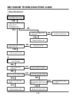
Page 60: ... sensor Check the syscon circuit NO YES YES YES YES NO NO 1 Deck Mechanism A NO NO NO No F R modes Is the present mode F R Mode Is the mode SW assembled correctly refer to page 4 13 Is the normal voltage supplied to the Capstan Motor Vcc1 Vcc2 Does terminal voltage Vctl of Capstan Motor supply side more than 4V Check the servo power circuits Replace the Capstan Motor Does the Capstan Motor rotate ...

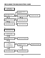
Page 61: ...page 4 13 Replace the Drum Motor Check the Servo Syscon Check the Syscon µ COM Cassette doesn t load Insert the cassette Check Lever Assembly S W Is there variation for CST IN S W Output In Tape with REC Tab L H L In Tape without REC Tab L H L H Does the CST IN S W work normally Does the Lever Assembly S W work normally Check the Syscon Circuit Check the Syscon Circuit Replace the CST IN S W YES Y...

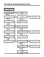
Page 62: ...k Check the Syscon Circuit Check the Syscon Circuit Check the Servo Syscon Does the Capstan Motor turn Is the terminal voltage vctl of the Drum Motor more than 4V Replace the Drum Motor Is the Vcc voltage of the Drum Motor normal Check the Clutch and Idler Assembly YES YES YES YES YES YES YES YES NO NO NO NO NO Is the terminal voltage vctl of Capstan Motor supplied more than 4V Replace the Capstan...

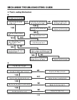
Page 63: ... 5V YES Is there a short circuit between cassette switch and GND on main P C Board Remove the short circuit part or Replace the main P C Board NO Check the Mode switch location and syscon circuit Replace the CST IN Switch YES NO YES NO NO Replace the CST IN Switch NO NO Cassette does not eject Does the L D Motor rotate in reverse Check the L D Motor or Drive IC Replace the Lever Assembly Switch Do...

Page 64: ...Assembly F L Check the power of L D Motor Check the Holder Assembly Cassette assembled correctly Replace the Gear Rack F L Does the Gear Assembly Rack F L work Does the Opener Door work Does the Arm Assembly F L work Does the L D Motor work Does the Holder Assembly Cassette move the Arm Assembly F L Replace the Front Loading Mechanism Assembly YES YES YES YES NO NO NO YES NO YES NO YES NO C ...

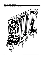
Page 65: ...4 28 EXPLODED VIEWS 117 103 105 117 100 106 107 A21 114 113 112 110 115 A24 116 102 A23 032 A22 109 054 054A 100A 100B 1 Front Loading Mechanism Section ...

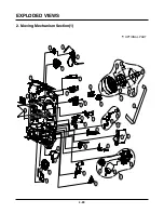
Page 66: ...29 401 402 001 008 011 031 079 017 032 024 406 020 021 028 019 018 029 030 026 A03 A04 A01 002 002A 025 027 022 003 004 006 007 010 405 014 015 009 409 013 023 016 405 012 402 OPTIONAL PART 2 Moving Mechanism Section 1 ...

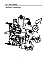
Page 67: ...EXPLODED VIEWS 4 30 051 052 517 061 056 058 518 052A 055 060 410 070 069 076 032 077 068 064 066 065 067 A11 078 A12 OPTIONAL PART 3 Moving Mechanism Section 2 ...

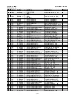
Page 68: ...Y P4 015 5870R 0005A OPENER LID D35 016 3041R 0036A BASE ASSEMBLY A C HEAD ALPS 017 4408R 0003A REEL S 018 4970R 0140A SPRING COIL RS D35 019 4421R 0008A BRAKE ASSEMBLY RS 020 4970R 0128A SPRING COIL D35 TB 021 4421R 0006A BRAKE ASSY T 022 6520D00002A HEAD CIRC D35 FE ST FE HEAD 023 3040R 0057A BASE LOADING 024 4261R 0024A ARM ASSEMBLY IDLER H 025 4810R 0111A BRACKET L D 026 4680R D006A MOTOR MECH...

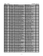
Page 69: ...ASSEMBLY CCD TL AT230M AABBDL1_ENG_POR_ 802 3890R C065K BOX MASTER TL AT130M AABBDL 1 803 3920R E016A PACKING Packing LV TL24I 0 02 0 EPS 10 804 3858R S001A SHEET MECH Packing LDPE 600M 630MM 0 5 VC 808 534 008C BATTERY MANGANESE AAAM R03 SEOTONG 1 5 V 1PA 900 6711R1P041H REMOTE CONTROLLER ASSEMBLY P9 LV TL1960 S AL LOCA NO PART NO DESCRIPTION SPECIFICATION REMARKS 079 3040R 0056A BASE TENSION D35...

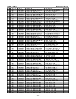
Page 70: ...1UF D 50V 80 20 F Y5V TA C173 0CE4764J638 CAPACITOR AL ELECTROLYTIC 47UF SRA SS 35V M FM5 TP 5 C301 0CN1040K948 CAPACITOR FIXED TUBULAR HIGH D 0 1UF D 50V 80 20 F Y5V TA C302 0CN1030F678 CAPACITOR TUBULA HIGH DIELE 0 01M 16V M Y TA26 C303 0CE1054K638 CAPACITOR ELECTROLYTIC 1 0M SRA SS50V M FM5 TP 5 C304 0CE2274C638 CAPACITOR ELECTROLYTIC 220M SRA 6 3V M FM5 TP 5 C305 0CN1040K948 CAPACITOR FIXED TU...

Page 71: ...TUBULAR HIGH DIELEC 0 022UF 50V Z F TA26 S C3G2 0CE4764F638 CAPACITOR ELECTROLYTIC 47M SRA SS 16V M FM5 TP 5 C3G3 0CN3320F668 CAPACITOR TUBULAR HIGH DIELEC 3300P 16V M TA26 C3G4 0CN4730K948 CAPACITOR FIXED TUBULAR High d 0 047UF D 50V 80 20 F Y5V C3G5 0CE4754K638 CAPACITOR FIXED ELECTROLYTIC 4 7UF SRA SS 50V 20 FM5 TP 5 C3G6 0CE4754K638 CAPACITOR FIXED ELECTROLYTIC 4 7UF SRA SS 50V 20 FM5 TP 5 C3G...

Page 72: ...1M 16V M Y TA26 C554 0CN1040K948 CAPACITOR FIXED TUBULAR HIGH D 0 1UF D 50V 80 20 F Y5V TA C555 0CE2264F638 CAPACITOR FIXED ELECTROLYTIC 22UF SRA SS 16V 20 FM5 TP 5 C557 0CN1040K948 CAPACITOR FIXED TUBULAR HIGH D 0 1UF D 50V 80 20 F Y5V TA C561 0CE4764C638 CAPACITOR ELECTROLYTIC 47M SRA 6 3V M FM5 TP 5 C567 0CN1020K518 CAPACITOR TUBULA HIGH DIELE 1000P 50V K B TA26 C570 0CC1200K415 CAPACITOR FIXED...

Page 73: ... L5 TP L405 0LR1000K035 INDUCTOR RADIAL LEAD 100M K 6X6 L5 TP L503 0LR1000K035 INDUCTOR RADIAL LEAD 100M K 6X6 L5 TP L504 0LA1000K018 INDUCTOR AXIAL LEAD 100M K 2 3X3 4 L5 TP L505 0LR1000K035 INDUCTOR RADIAL LEAD 100M K 6X6 L5 TP L901 0LA1000K018 INDUCTOR AXIAL LEAD 100M K 2 3X3 4 L5 TP L902 0LA1000K018 INDUCTOR AXIAL LEAD 100M K 2 3X3 4 L5 TP L904 0LR1000K035 INDUCTOR RADIAL LEAD 100M K 6X6 L5 TP...

Page 74: ...0000B IC ROHM ICP N10 T104 TP IC DETACT IC101 0ISK615300A IC SANKEN STR G6153T 5PIN FM CUT BK PWM IC103 0ISS431000A IC SAMSUNG ELECTRONICS KA431AZ LM431AZ IC301 0ISA715820A IC SANYO LA71582M 100QFP BK AVCP TIMELA IC3G1 0IMA391600A IC MATSUSHITA AN3916 SDIP ST AGC IC IC501 0IMCRMA024B IC MICRO CONTROLLER MN101D06F LE 2ND MATSUSHITA 10 IC503 0ICS241600B IC CATALYST CAT24WC16P 8P DIP ST 16K SERIA IC5...

Page 75: ...HM 1 6 W 5 TA26 R313 0RD2700F608 RESISTOR FIXED CARBON FILM 270 OHM 1 6 W 5 TA26 R316 0RD1500F608 RESISTOR FIXED CARBON FILM 150 OHM 1 6 W 5 TA26 R317 0RD6802F608 RESISTOR FIXED CARBON FILM 68K OHM 1 6 W 5 TA26 R318 0RD1001F608 RESISTOR FIXED CARBON FILM 1K OHM 1 6 W 5 TA26 R319 0RD1001F608 RESISTOR FIXED CARBON FILM 1K OHM 1 6 W 5 TA26 R320 0RD1501F608 RESISTOR FIXED CARBON FILM 1 5K OHM 1 6 W 5 ...

Page 76: ...TA26 R493 0RD0102F608 RESISTOR FIXED CARBON FILM 10 OHM 1 6 W 5 TA26 R501 0RD2200F608 RESISTOR FIXED CARBON FILM 220 OHM 1 6 W 5 TA26 R502 0RD2200F608 RESISTOR FIXED CARBON FILM 220 OHM 1 6 W 5 TA26 R504 0RD1001F608 RESISTOR FIXED CARBON FILM 1K OHM 1 6 W 5 TA26 R505 0RD1001F608 RESISTOR FIXED CARBON FILM 1K OHM 1 6 W 5 TA26 R507 0RD1201F608 RESISTOR FIXED CARBON FILM 1 2K OHM 1 6 W 5 TA26 R508 0R...

Page 77: ...1F608 RESISTOR FIXED CARBON FILM 1K OHM 1 6 W 5 TA26 R591 0RD4701F608 RESISTOR FIXED CARBON FILM 4 7K OHM 1 6 W 5 TA26 R592 0RD4702F608 RESISTOR FIXED CARBON FILM 47K OHM 1 6 W 5 TA26 R593 0RD1202F608 RESISTOR FIXED CARBON FILM 12K OHM 1 6 W 5 TA26 R595 0RD1000F608 RESISTOR FIXED CARBON FILM 100 OHM 1 6 W 5 TA26 R596 0RD1000F608 RESISTOR FIXED CARBON FILM 100 OHM 1 6 W 5 TA26 R597 0RD1000F608 RESI...

Page 78: ...RD1001F608 RESISTOR FIXED CARBON FILM 1K OHM 1 6 W 5 TA26 R909 0RD1001F608 RESISTOR FIXED CARBON FILM 1K OHM 1 6 W 5 TA26 R910 0RD1001F608 RESISTOR FIXED CARBON FILM 1K OHM 1 6 W 5 TA26 R911 0RD1001F608 RESISTOR FIXED CARBON FILM 1K OHM 1 6 W 5 TA26 R912 0RD1001F608 RESISTOR FIXED CARBON FILM 1K OHM 1 6 W 5 TA26 R914 0RD1001F608 RESISTOR FIXED CARBON FILM 1K OHM 1 6 W 5 TA26 R915 0RD1001F608 RESIS...

Page 79: ...OSTECH DC 12 V 5 SW617 556 219B SWITCH TACT THVV502GAA POSTECH DC 12 V 5 SW618 556 219B SWITCH TACT THVV502GAA POSTECH DC 12 V 5 SW619 556 219B SWITCH TACT THVV502GAA POSTECH DC 12 V 5 SW620 556 219B SWITCH TACT THVV502GAA POSTECH DC 12 V 5 SW621 556 219B SWITCH TACT THVV502GAA POSTECH DC 12 V 5 SW901 556 219B SWITCH TACT THVV502GAA POSTECH DC 12 V 5 TRANSISTOR Q152 0TR320309AA TRANSISTOR BIPOLARS...

Page 80: ... TRANSFORMER T101 642 023U TRANSFORMER SMPS COIL SJE 023U SJ CS WIDE EER2828 VARISTOR V101 656 004C VARISTOR DRAWING SVC681D 10A SAMHWA 4 O CUT X TAL X302 6202R2357AE RESONATOR CRYSTAL HC49U SSANG TAE 3 579575MHZ 1 X501 6202R DA01A RESONATOR CRYSTAL CFS 308 CITIZEN 32 768KHZ 20 X502 6202R1143DC RESONATOR CRYSTAL H49U BUBANG 14 31818HZ 25PPM 1 ZENER DIODE ZD101 0DZ332609FA DIODE ZENER UZ 3 3BSB 26M...

Reviews: