4-25
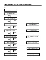
MECHANISM TROUBLESHOOTING GUIDE
In PB mode Tape Presence
not sensed.
Is the Pinch Roller attached
to the Capstan Motor Shaft?
Check Alignment positions
(page 4-13).
Does the T/Up Reel turn?
Replace the Belt.
Is the Belt ok?
Does the Drum Motor turn?
Are there DPG, DFG pulses?
Are the T/Up and Supply Reel
Sensors ok?
Check the Syscon, Circuit.
Check the Syscon, Circuit.
Check the Servo, Syscon.
Does the Capstan Motor turn?
Is the terminal voltage(vctl) of the
Drum Motor more than 4V?
Replace the
Drum Motor.
Is the Vcc voltage of the Drum
Motor normal?
Check the Clutch and Idler
Assembly.
YES
YES
YES
YES
YES
YES
YES
YES
NO
NO
NO
NO
NO
Is the terminal voltage(vctl) of
Capstan Motor supplied more
than 4V?
Replace the Capstan Motor.
Is the voltage supplied to the
Capstan Motor Vcc1,Vcc2 each?
YES
YES
YES
Check the Servo, Power.
NO
NO
NO
E.
Summary of Contents for TL-AT130M
Page 23: ...3 14 3 13 SECTION3 ELECTRICAL BLOCK CIRCUIT DIAGRAMS 1 OVERALL WIRING DIAGRAM ...
Page 24: ...3 16 3 15 SECTION3 ELECTRICAL BLOCK CIRCUIT DIAGRAMS 2 POWER BLOCK DIAGRAM ...
Page 25: ...3 18 3 17 SECTION3 ELECTRICAL BLOCK CIRCUIT DIAGRAMS 3 POWER CLRCUIT DIAGRAM ...
Page 26: ...3 19 SECTION3 ELECTRICAL BLOCK CIRCUIT DIAGRAMS 4 AUDIO BLOCK DIAGRAM ...
Page 27: ...3 20 SECTION3 ELECTRICAL BLOCK CIRCUIT DIAGRAMS 5 Y C BLOCK DIAGRAM ...
Page 28: ...3 22 3 21 SECTION3 ELECTRICAL BLOCK CIRCUIT DIAGRAMS 6 A V CIRCUIT DIAGRAM ...
Page 29: ...3 23 SECTION3 ELECTRICAL BLOCK CIRCUIT DIAGRAMS ...
Page 30: ...3 25 3 24 SECTION3 ELECTRICAL BLOCK CIRCUIT DIAGRAMS 7 SYSTEM BLOCK DIAGRAM ...
Page 31: ...3 26 SECTION3 ELECTRICAL BLOCK CIRCUIT DIAGRAMS ...
Page 32: ...3 28 3 27 SECTION3 ELECTRICAL BLOCK CIRCUIT DIAGRAMS 8 SYSTEM CLRCUIT DIAGRAM ...
Page 33: ...3 30 3 29 SECTION3 ELECTRICAL BLOCK CIRCUIT DIAGRAMS 9 JACK CLRCUIT DIAGRAM ...
Page 34: ...3 32 3 31 SECTION3 ELECTRICAL BLOCK CIRCUIT DIAGRAMS 10 KEY BOARD CLRCUIT DIAGRAM ...
Page 35: ...3 34 3 33 SECTION3 ELECTRICAL PRINTED CIRCUIT DIAGRAMS 1 MAIN P C BOARD ...

