background image

WB21LMB

WB21LMC

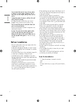
Please read this manual carefully before operating your set and retain it for future reference.

Wall Mount Bracket

Safety and Reference

OWNER’S MANUAL

Printed in Korea

www.lg.com

Copyright   2021 LG Electronics Inc. All Rights Reserved.

*MFL71772403*

(2106-REV02)

Summary of Contents for WB21LMB

Page 1: ...anual carefully before operating your set and retain it for future reference Wall Mount Bracket Safety and Reference OWNER S MANUAL Printed in Korea www lg com Copyright 2021 LG Electronics Inc All Rights Reserved MFL71772403 2106 REV02 ...

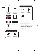
Page 2: ... stud 3 2 39 mm 1 5 inches Concrete wall 2 2 45 mm 1 7 inches Wood stud TV protection cushion B 2 pcs Guide Spacer Fixing Screws 2 pcs M6 x L45 Guide Spacer 2 pcs Precautions for Safety Professional installers should read this manual carefully to ensure proper installation Professional installers should forward this manual to customers after installation and encourage them to read and store it in ...

Page 3: ...the product according to the instructions in the installation manual Failure to install the product according to the instructions in the installation manual can result in serious personal injury or product damage Be sure to have at least four people when install ing the product or adjusting the product s height Attempting to perform installation or adjustments personally may result in personal inj...

Page 4: ...erboard plywood brick etc is not recommended since there is a greater chance the product will fall When installing the Full Contact Wall Mount the TV may not be contacted firmly against the wall due to some wall conditions Install the product only on a vertical wall Do not install on a tilted wall that exceeds building standards or on the heavily titled wall or ceiling LG is not responsible for pr...

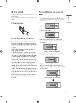
Page 5: ... finishing material Since the anchors provided with this product may not be suitable for your wall material be sure to check with a professional before attempting installation Other unspecified walls must be capable of support ing pullout loads of over 70 kgf 154 3 lbf 686 N and shear loads of over 100 kgf 220 4 lbf 980 N per fastener Use an Ø 8 mm drill bit for concrete and a hammer impact drill ...

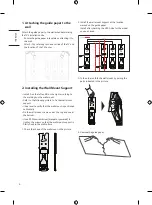
Page 6: ...he following picture to fix the wall mount support Use a level to verify that the wall mount is positioned horizontally Fix the wall mount screws one at the top and one at the bottom Use a Phillips screwdriver manual or powered to tighten the screws so that the wall mount support is firmly fixed to the wall surface 1 Check the shape of the wall mount in the picture 2 Install the wall mount support...

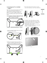
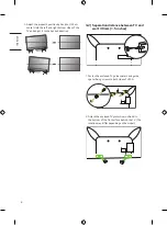
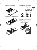
Page 7: ... sides of the top of VESA on the TV 2 Attach the enclosed TV protective cushion A to the bottom of the flat surface behind the TV The location may differ depending on the model 3 After attaching the TV to the mount on the wall fasten the screws fixed to the TV to the wall mount 4 Push the TV close to the wall Be sure to gently push the upper and lower parts of the TV so that the pushing doesn t af...

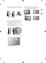
Page 8: ... adjust it to the desired direction 3 2 Separation distance between TV and wall 39 mm 1 5 inches 1 Fasten the enclosed TV guide spacers and guide spacer fixing screws to both sides of VESA 2 Attach the enclosed TV protective cushion B to the bottom of the flat surface behind the TV The location may differ depending on the model ...

Page 9: ...rts of the TV so that the pushing doesn t affect the TV Gently push the upper center of the TV once again until it s com pletely pressed against the wall Caution Do not apply excessive force to the screen Doing so can damage the screen 39 mm 1 5 inches 5 Adjust the product s position by hand so it s hori zontal Hold the left and right bottom sides of the TV and adjust it to the desired direction ...

Page 10: ...ide and plug it into the TV Position your body as close to the wall as possible behind the TV and organize the cables using the holder The location of the cable connection terminal may differ depending on the model 3 Push the TV close to the wall Be sure to gently push the upper and lower parts of the TV so that the pushing doesn t affect the TV Gently push the upper center of the TV once again un...

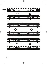
Page 11: ...ble by referring to the assembly guide paper which is provided as an accessory 3 Check the screw fixing positions by marking the Wall mounting supporter screw points indicated by the left and right centers of the wood studs Wall Mounting Supporter Point Wall Mounting Bracket Point Japan When installing on a wooden wall VESA Size 200 A A A A B B B B When installing on a wooden wall VESA Size 300 A ...

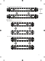
Page 12: ...ISH _index When installing on a wooden wall VESA Size 400 A A A A B B B B Australia When installing on a wooden wall VESA Size 200 A A A A B B B B When installing on a wooden wall VESA Size 300 A A A A B B B B ...

Page 13: ...H _index When installing on a wooden wall VESA Size 400 A A A A B B B B North America When installing on a wooden wall VESA Size 200 B B B B A A A A When installing on a wooden wall VESA Size 300 A A A A B B B B ...

Page 14: ...14 ENGLISH _index When installing on a wooden wall VESA Size 400 A A A A B B B B ...

Page 15: ...l mounting supporter 4 Align the hole in the wall mount support with the hole in the Wall mounting supporter 5 Insert the wall mount support screw into the hole in the wall mount support and Wall mounting support er Tighten the screw while holding the wall mount support with your hand 1 Loosely tighten the screws turning just 2 to 3 times before placing the wall mount 2 Tighten until it is complet...

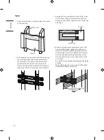
Page 16: ...ll a hole 76 mm 2 9 inches or deeper into the screw locations marked on the wall for the wall mount Clean the drill holes Drywall Wood stud 76 mm 2 9 inches 4 Position the wall mount assembly so that it fits over the drilled holes Tighten the wall mount screws for the Wall mounting fixing screws into the drill holes At this time tighten the screws so that the wall wall mounting assembly and wall m...

Page 17: ...rill a hole 76 mm 2 9 inches or deeper into the screw locations marked on the wall for the wall mount Clean the drill holes Drywall Wood stud 76 mm 2 9 inches 4 Position the wall mount assembly so that it fits over the drilled holes Tighten the wall mount screws for the Wall mounting fixing screws into the drill holes At this time tighten the screws so that the wall wall mounting assembly and wall...

Page 18: ... drill a hole 76 mm 2 9 inches or deeper into the screw locations marked on the wall for the wall mount Clean the drill holes Drywall Wood stud 76 mm 2 9 inches 4 Position the wall mount assembly so that it fits over the drilled holes Tighten the wall mount screws for the Wall mounting fixing screws into the drill holes At this time tighten the screws so that the wall wall mounting assembly and wa...

Page 19: ...h sides of the top of VESA on the TV 2 Attach the enclosed TV protective cushion A to the bottom of the flat surface behind the TV The location may differ depending on the model 3 After attaching the TV to the mount on the wall fasten the screws fixed to the TV to the wall mount 4 Push the TV close to the wall Be sure to gently push the upper and lower parts of the TV so that the pushing doesn t a...

Page 20: ... adjust it to the desired direction 2 2 Separation distance between TV and wall 45 mm 1 7 inches 1 Fasten the enclosed TV guide spacers and guide spacer fixing screws to both sides of VESA 2 Attach the enclosed TV protective cushion B to the bottom of the flat surface behind the TV The location may differ depending on the model ...

Page 21: ...rts of the TV so that the pushing doesn t affect the TV Gently push the upper center of the TV once again until it s com pletely pressed against the wall Caution Do not apply excessive force to the screen Doing so can damage the screen 45 mm 1 7 inches 5 Adjust the product s position by hand so it s hori zontal Hold the left and right bottom sides of the TV and adjust it to the desired direction ...

Page 22: ... 285 9 11 2 176 5 6 9 117 4 6 126 4 9 25 0 9 93 3 3 6 9 2 267 8 10 5 Model Name WB21LMB Width mm inches 73 7 2 9 Height mm inches 285 9 11 2 Depth mm inches 13 0 5 Product Weight kg lbs 0 6 1 3 x 2 Screws Distance mm 65 200 300 400 Max Tensile Load kg lbs 50 110 2 ...

Page 23: ...23 ENGLISH _index Australia Japan When not removing the wall mount support VESA 200 700 27 5 200 7 8 VESA 300 700 27 5 300 11 8 ...

Page 24: ...24 ENGLISH _index 99 3 3 9 9 2 267 8 10 5 19 0 7 VESA 400 700 27 5 285 9 11 2 206 8 1 77 3 0 46 1 8 80 3 1 400 15 7 31 1 2 31 1 2 ...

Page 25: ...25 ENGLISH _index North America When not removing the wall mount support VESA 200 80 3 1 206 8 1 285 9 11 2 77 3 0 31 1 2 460 18 1 200 7 8 31 1 2 VESA 300 460 18 1 300 11 8 ...

Page 26: ...26 ENGLISH _index VESA 400 700 27 5 400 15 7 285 9 11 2 206 8 1 77 3 0 46 1 8 80 3 1 31 1 2 31 1 2 99 3 3 9 9 2 267 8 10 5 19 0 7 ...

Page 27: ...19 0 7 Product Weight kg lbs 3 6 7 9 Screws Distance mm 65 200 300 400 Max Tensile Load kg lbs 50 110 2 North America When not removing the wall mount support Model Name WB21LMB Width mm inches 460 18 1 Height mm inches 285 9 11 2 Depth mm inches 19 0 7 Product Weight kg lbs 2 8 6 1 Screws Distance mm 65 200 300 Max Tensile Load kg lbs 50 110 2 North America When not removing the wall mount suppor...

Page 28: ......

Reviews: