background image

INSTALLATION MANUAL

WALL OVEN

Read this installation manual thoroughly before installing the 

appliance and keep it handy for reference at all times.

ENGLISH

WDES9428F, WSES4728F

MFL51224812

Rev.00_072721

www.lg.com

Copyright © 2021 LG Electronics Inc. All Rights Reserved.

œš†”ˆ•U‰––’U‰––’GGwˆŽŒGXGG{œŒš‹ˆ SGqœ“ GY^SGYWYXGGYaYXGwt

Summary of Contents for WDES9428F

Page 1: ...on manual thoroughly before installing the appliance and keep it handy for reference at all times ENGLISH WDES9428F WSES4728F MFL51224812 Rev 00_072721 www lg com Copyright 2021 LG Electronics Inc All Rights Reserved U U GGw GXGG SGq GY SGYWYXGGYaYXGwt ...

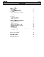
Page 2: ...ON 4 Before Installing 4 Proper Location and Dimensions 11 Parts Tools 12 Installing the Oven and Test Run 12 Unpacking and Removing Oven Doors and Bottom Trim 13 Electrical Requirements 13 Making Electrical Connections 15 Installing Oven and Assembling Oven Doors and Bottom Trim 16 Test the Oven Before Use U U GGw GYGG SGq GY SGYWYXGGYaYXGwt ...

Page 3: ...se aluminum foil or any other material to line the oven bottom Improper installation of oven liners may result in a risk of electric shock or fire Make sure your appliance is properly installed and grounded by a qualified installer according to the installation instructions Any adjustment and service should be performed only by qualified installers or service technicians Be certain that all packin...

Page 4: ...heat buildup that may result in heat damage or fire The information in this manual should be followed exactly Failure to do so could result in fire or electrical shock causing property damage personal injury or death DO NOT put any weight on the oven door Never allow anyone to climb sit stand or hang on the oven door The oven could be tipped and injury might result from contact with hot food or th...

Page 5: ...eight 29 7 16 74 7 cm 52 1 16 132 3 cm B Width 29 3 4 75 5 cm 29 3 4 75 5 cm C Depth 23 3 8 59 3 cm 23 3 8 59 3 cm D Height standard installation 29 73 6 cm 51 9 16 131 0 cm E Height power cord 27 1 2 70 0 cm 50 5 16 127 7 cm F Length power cord 60 152 4 cm 60 152 4 cm G Width back 27 3 8 695 3 mm 27 3 8 695 3 mm H Width standard installation 28 7 16 72 2 cm 28 7 16 72 2 cm D E F A B C J I K N P M...

Page 6: ...13 16 Min 131 6 cm 51 15 16 Max 131 9 cm N Cutout depth 24 Min 61 0 cm 24 Min 61 0 cm O Cutout location from floor 31 78 7 cm 12 30 5 cm P Height of conduit opening from floor of cutout 23 1 2 59 7 cm 47 119 4 cm Q Distance of conduit opening from side of cabinet 5 12 7 cm 5 12 7 cm SINGLE BUILT IN OVEN DOUBLE BUILT IN OVEN a Junction box b Conduit opening c Cleat Spacer List Dimensions Single wal...

Page 7: ... B Cleat spacer inset from front of cabinet 1 3 8 3 5 cm 1 3 8 3 5 cm C Cleat spacer width 3 16 0 5 cm 3 16 0 5 cm D Cleat spacer depth 1 2 5 cm 1 2 5 cm E Depth of open door 23 58 4 cm 23 58 4 cm F Bottom of cutout from floor 31 78 7 cm 12 30 5 cm G Cutout depth 25 63 5 cm 25 63 5 cm H Cutout height 29 5 8 75 2 cm 52 5 16 132 9 cm I Cleat spacer height 28 9 16 72 6 cm 51 9 32 130 3 cm J Height of...

Page 8: ...abel on top of oven for approved cooktop models b 240 V 208 V junction box location Junction box may be in adjacent cabinet c Gas and electrical connections for 30 76 2 cm gas cooktop must be located in an adjacent accessible location to the right For a 36 91 4 cm gas cooktop the connections may be made to the left a Cover Bracket b 4X22 Tapping Screw U U GGw G_GG SGq GY SGYWYXGGYaYXGwt ...

Page 9: ...a Gas or electric cooktops may be installed over this oven See cooktop installation instructions for cutout size See label on top of oven for approved cooktop models b 240 V 208 V junction box location Junction box may be in adjacent cabinet c Gas and electrical connections for 30 76 2 cm gas cooktop must be located in an adjacent accessible location to the right For a 36 91 4 cm gas cooktop the c...

Page 10: ...10 INSTALLATION i 36 91 3 cm typical countertop height j 1 1 8 2 9 cm bottom of vent trim Decor to vent opening U U GGw GXWGG SGq GY SGYWYXGGYaYXGwt ...

Page 11: ...er brackets for flush installation e 4X10 2 Screws for vent trim Decor f Vent trim Decor Parts Not Provided a Junction box b Wire nuts c 3 4 Conduit connector d 36 91 cm String Tools Needed a Phillips screwdriver b Flat blade screwdriver c Tape measure d Pliers e Drill f Gloves NOTE Observe all governing codes and ordinances Have the installer show you the location of the circuit breaker or fuse M...

Page 12: ...oven but is an added convenience Unpacking Materials Remove any packing material from the oven before installing the oven 1 Remove all tape from around the oven 2 Open the oven door and remove the packaging materials and oven racks inside the oven Removing Oven Door 1 Fully open the door 2 Unlock the hinge locks rotating them as far toward the open door frame as they will go a Slot b Hinge lock c ...

Page 13: ...nector If the flexible conduit will not fit within the connector do not install the oven until a connector of the proper size is obtained NOTE The power leads supplied with the appliance are UL CSA recognized for connection to larger gauge household wiring The insulation of these leads is rated at temperatures much higher than the temperature rating of household wiring The current carrying capacit...

Page 14: ...y b Black wires c White wires d Red wires e Green or bare ground wires f 4 wire flexible conduit from oven 1 Connect the oven ground green wire and neutral white wire to the branch circuit neutral white or gray wire using a wire nut 2 Connect the oven red wire to the branch circuit red L2 wire in accordance with local codes using a wire nut 3 Connect the oven black wire to the branch circuit black...

Page 15: ...efully push against the oven front frame Do not push against the outside edges While sliding the oven back pull the string so that the conduit lies on the top of the oven in a natural loop When you are sure the conduit is out of the way slide the oven 3 4 of the way back into the opening Remove the string by pulling on one end of the loop 3 Secure the oven Using the mounting holes a on the oven si...

Page 16: ...be available 1 Turn on the power supply The initial signal sound will be heard 2 Check the operation of the broil mode When the oven is set to broil the upper element in the oven should become red After a few minutes partially open the oven door You should feel heat from the oven Touch Stop 3 Check the operation of the bake mode After setting the oven to 350 ૢ 177 for baking the temperature of the...

Page 17: ...ncludes common occurrences that are not the result of defective workmanship or materials in this product If the problem occurs continuously contact the dealer Refer to the warranty in the owner s manual for the LG toll free service number and address U U GGw GX GG SGq GY SGYWYXGGYaYXGwt ...

Page 18: ...18 Memo U U GGw GX_GG SGq GY SGYWYXGGYaYXGwt ...

Page 19: ...ente el manual de instalación antes de instalar el aparato y consérvelo a mano en todo momento para su referencia ESPAÑOL WDES9428F WSES4728F www lg com Copyright 2021 LG Electronics Inc Todos los derechos reservados U U GGw GXGG SGq GY SGYWYXGGYaZWGwt ...

Page 20: ...5 Dimensiones y ubicación adecuadas 12 Piezas Herramientas 13 Instalación y prueba de funcionamiento del horno 13 Desembalaje y extracción de las puertas y el reborde inferior del horno 14 Requisitos eléctricos 15 Conexiones eléctricas 16 Instalación del horno y colocación de las puertas y el reborde inferior del horno 18 Pruebe el horno antes de usarlo U U GGw GYGG SGq GY SGYWYXGGYaZWGwt ...

Page 21: ...s permanentes al interior del horno el papel de aluminio se fundirá en la superficie interior del horno No utilice papel de aluminio ni ningún otro material para revestir la base del horno La instalación inadecuada de los revestimientos del horno podría causar riesgo de descarga eléctrica o incendio Haga que un instalador calificado instale y conecte a tierra su electrodoméstico de manera apropiad...

Page 22: ...cta del cableado doméstico de aluminio a los cables de cobre puede provocar descargas eléctricas o un incendio Utilice únicamente conectores diseñados para unir cobre con aluminio y siga al pie de la letra el procedimiento recomendado por el fabricante U U GGw G GG SGq GY SGYWYXGGYaZWGwt ...

Page 23: ...iva de calor que puede provocar daños o un incendio La información en este manual se debe seguir exactamente Si no se hace podría tener como resultado incendio o descarga eléctrica causar daños a la propiedad lesiones personales o la muerte NUNCA coloque peso sobre la puerta del horno Nunca permita que nadie se suba siente pare o cuelgue de la puerta del horno El horno se podría inclinar y podría ...

Page 24: ...orno con pared simple Horno con pared doble A Alto 29 7 16 74 7 cm 52 1 16 132 3 cm B Ancho 29 3 4 75 5 cm 29 3 4 75 5 cm C Profundidad 23 3 8 59 3 cm 23 3 8 59 3 cm D Alto instalación estándar 29 73 6 cm 51 9 16 131 0 cm E Alto cable de alimentación 27 1 2 70 0 cm 50 5 16 127 7 cm F Largo cable de alimentación 60 152 4 cm 60 152 4 cm G Ancho posterior 27 3 8 695 3 mm 27 3 8 695 3 mm D E F A B C J...

Page 25: ...1 cm Mín 51 13 16 131 6 cm Máx 51 15 16 131 9 cm N Profundidad del corte Mín 24 61 0 cm Mín 24 61 0 cm O Ubicación del corte respecto del piso 31 78 7 cm 12 30 5 cm P Alto de la abertura del conducto desde el piso del corte 23 1 2 59 7 cm 47 119 4 cm P Distancia de la abertura del conducto desde el lateral del gabinete 5 12 7 cm 5 12 7 cm HORNO EMPOTRADO SIMPLE HORNO EMPOTRADO DOBLE a Caja de cone...

Page 26: ... frontal del gabinete 1 3 8 3 5 cm 1 3 8 3 5 cm C Ancho de la abrazadera espaciador 3 16 0 5 cm 3 16 0 5 cm D Profundidad de la abrazadera espaciador 1 2 5 cm 1 2 5 cm E Profundidad de la puerta abierta 23 58 4 cm 23 58 4 cm F Parte inferior del corte desde el piso 31 78 7 cm 12 30 5 cm G Profundidad del corte 25 63 5 cm 25 63 5 cm H Alto del corte 29 5 8 75 2 cm 52 5 16 132 9 cm I Alto de la abra...

Page 27: ...9 INSTALACIÓN ESPAÑOL HORNO EMPOTRADO SIMPLE HORNO EMPOTRADO DOBLE a Soporte de la cubierta b Tornillo roscante de 4X22 U U GGw G GG SGq GY SGYWYXGGYaZWGwt ...

Page 28: ...ar accesible y adyacente a la derecha Para una placa de cocción a gas de 36 91 4 cm las conexiones se deben realizar a la izquierda d Se pueden necesitar rellenos laterales y superiores si la unidad está posicionada entre gabinetes existentes Asegúrese de que estén sujetos de manera segura porque sujetarán el horno en los gabinetes e Mín 29 1 8 74 0 cm Máx 29 3 16 74 1 cm f Permita una superposici...

Page 29: ...ra la placa de cocción a gas de 30 76 2 cm se debe ubicar en un lugar accesible y adyacente a la derecha Para una placa de cocción a gas de 36 91 4 cm las conexiones se deben realizar a la izquierda d Se pueden necesitar rellenos laterales y superiores si la unidad está posicionada entre gabinetes existentes Asegúrese de que estén sujetos de manera segura porque sujetarán el horno en los gabinetes...

Page 30: ...nillos de 4X10 para el reborde de ventilación decoración f Reborde de ventilación decoración Piezas no incluidas a Caja de conexiones b Conectores de torsión c Conector de conducto de 3 4 d 36 91 cm de cuerda Herramientas necesarias a Destornillador Phillips b Destornillador plano c Cinta medidora d Pinzas e Taladro f Guantes NOTA Cumpla todos los códigos y ordenanzas vigentes Solicite al instalad...

Page 31: ...os productos pueden dañar la superficie del electrodoméstico La eliminación de la puerta no es un requisito para la instalación del horno pero es una conveniencia agregada Materiales de embalaje Retire todos los materiales de embalaje del horno antes de proceder a su instalación 1 Retire toda la cinta de alrededor del horno 2 Abra la puerta del horno y retire los materiales de embalaje y los estan...

Page 32: ...circuito central o de conexión a tierra La caja de conexiones debe contar con un conector de conductos homologado por UL El electrodoméstico debe contar con cableado de conexión permanente cableado directo a una caja de conexiones aprobada En estos productos no se permite la conexión del tipo enchufe y receptáculo NO acorte el conducto flexible El conector de conductos debe quedar bien sujeto a la...

Page 33: ...ermiten la conexión del conductor a tierra desde el marco al cable neutral blanco siga las instrucciones de conexión para un circuito de 4 hilos Conexión de circuito de 3 hilos al suministro de energía doméstico ADVERTENCIA El hilo del medio neutro o tierra que es blanco de un cable de alimentación de 3 hilos o un conducto de 3 hilos se debe conectar al poste medio del bloque de terminales princip...

Page 34: ...jo del circuito derivado L2 en cumplimiento con los códigos locales utilizando un conector de torsión 5 Conecte el cable negro del horno al cable negro del circuito derivado L1 en cumplimiento con los códigos locales utilizando un conector de torsión 6 Instale la tapa de la caja de conexiones Instalación del horno y colocación de las puertas y el reborde inferior del horno Instalación del horno In...

Page 35: ...la puerta Si la puerta no se abre por completo la hendidura no está bien apoyada en el borde inferior de las ranuras 4 Bloquee las trabas d girándolas nuevamente hacia las ranuras del marco del horno hasta que se cierren correctamente 5 Cierre la puerta del horno NOTA Use ambas manos para quitar la puerta del horno Cuando instale la puerta del horno tenga cuidado de no golpear el reborde inferior ...

Page 36: ...top Detener 4 Verifique el funcionamiento del modo Convection Bake Hornear por convección Luego de configurar el horno en 350 ૢ 177 para hornear por convección se debe poner en marcha el ventilador dentro del horno con la puerta cerrada Pulse Stop Detener 5 Encienda y apague la luz del horno para comprobar que las luces se encuentran en condiciones 6 Verifique el funcionamiento del quemador para c...

Page 37: ...19 Memorándum U U GGw GX GG SGq GY SGYWYXGGYaZWGwt ...

Page 38: ...20 Memorándum U U GGw GYWGG SGq GY SGYWYXGGYaZWGwt ...

Page 39: ...21 Memorándum U U GGw GYXGG SGq GY SGYWYXGGYaZWGwt ...

Page 40: ...LG Customer Information Center Register your product Online www lg com For inquiries or comments visit www lg com or call 1 800 243 0000 U S A 1 888 542 2623 CANADA U U GGw GX GG SGq GY SGYWYXGGYaZWGwt ...

Reviews: