background image

TRAINING MANUAL 


WM0742HGA 


WM0742HGA Page 

26 

TRAINING 

MANUAL 


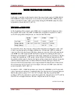
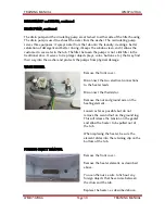
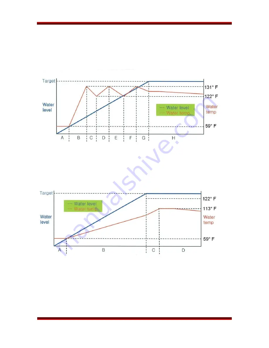
Prewash valve opens, cold water is supplied. 

B, D, and F 

Hot valve opens to raise the water temperature to 131

°

 F.  

C, E, and G 

Cold valve opens to lower the water temperature to 122

°

 F. 


No water is supplied because the water level reaches the target. 


Example 1 


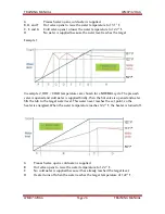
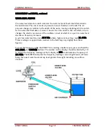
In example 2, HOT / COLD temperatures are chosen for a NORMAL cycle. The prewash 

valve is opened and cold water is supplied briefly, then the hot valve is opened and water 
fills the tub to the target water level. This water never reaches the set point, so the 
heater is energized. When the water temperature reaches 122

°

 F, the heater is turned off.  


Prewash valve opens, cold water is supplied. 

Hot valve opens to raise the water temperature to 122

°

 F.  

No cold water is supplied because it has already reached the target level. 

D  

Heater turns off when the water reaches the target temperature of 122

°

 F. 

Summary of Contents for WM0742HGA

Page 1: ...LG TRAINING MANUAL LG TRAINING MANUAL Steam Washer WM0742H A Fall 2008 ...

Page 2: ...ademy com Technical training Contact Number Hours of Operation Customer Service 800 243 0000 24 7 365 days a year Technical Support 800 847 7597 7am 7pm Mon Fri Sat 8 2 CST Parts Sales 888 393 6484 7am 7pm Mon Sat CST Training Center 256 774 4051 8am 5pm Mon Fri CST Published August 2008 by LG Electronics USA Trainng Center Copyright 2008 LG Electronics of Alabama Inc Phone Contacts Web Contacts ...

Page 3: ... metal in the appliance Before removing a replacement part from its package touch the anti static bag to a ground connection point or unpainted metal in the appliance Handle the electronic control assembly by its edges only When repackaging a failed electronic control assembly in an anti static bag observe these same precautions REGULATORY INFORMATION This equipment has been tested and found to co...

Page 4: ...onnections 14 Water 14 Drain 14 Electrical 14 Pedestal Installation 15 Control Panel 17 Program Chart 18 Service Safety Warnings 18 Cycle and Option Chart 19 Cycle and Option Information 20 Water Temperature Control 25 Wiring Diagram 27 Dispenser 28 Dispenser Hose Connection Chart 30 Direct Drive Motor 31 Disassembly and Repair 32 Block Wiring Diagram 32 Control Panel 33 Top Cover 33 Dispenser 34 ...

Page 5: ...sis and Check List 56 No Power No Water Input IE 56 Door Error dE Drain Trouble OE 57 Oversudsing No Softening Error Codes PE FE tE and LE 58 Fault Diagnosis and Troubleshooting 59 No Power 59 Vibration and Noise In Spin Cycle 60 No Water Supply 61 Detergent Fails To Dispense 61 Liquid Detergent Bleach Softener Fail To Dispense 62 Heating Without Water 63 Drain Malfunction 63 Wash Heater Malfuncti...

Page 6: ...TRAINING MANUAL WM0742HGA WM0742HGA Page 4 TRAINING MANUAL INTRODUCTION The WM0742HGA is a top of the line front loader with the optional cycles of Allergiene Steam and Tub Clean SPECIFICATIONS ...

Page 7: ...HGA Page 5 TRAINING MANUAL WARRANTY Warranty statements vary by product Be sure to check the warranty that was included with the product because that is the valid warranty This statement is generic and for instructional purposes only ...

Page 8: ...LTED DRUM LARGE DOOR The tilted drum 10 and large door opening allow easier loading and unloading STEAM WASHING STEAMFRESH The steam feature works with the recirculating pump to increase washing performance while maintaining low energy and water usage STEAMFRESH is not a wash cycle but uses steam to remove wrinkles from previously laundered dry clothes ROLLER JETS and BALLS The baffles pick up wat...

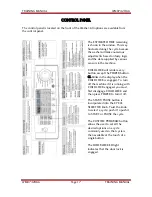
Page 9: ... the controls Children then cannot play with the buttons and disturb the wash cycle See additional information on page 23 CONTROLS 1 Power Button Turns the machine on or off 2 Cycle Start Button Starts or pauses the machine 3 Custom Program Button Sets an often used program for convenience 4 Setting Override Buttons Overrides the standard settings for a cycle 5 Delay Wash Button Sets the delay to ...

Page 10: ...an automatic electrically operated lock system When the machine is off or paused the door can be opened by pulling it When the machine is operating the electric latch keeps the door closed The door cannot be opened When the WASHER is operating When the power failed or the washer is unplugged until the capacitor discharges and releases the lock When the DOOR LOCK light is on When the drum is still ...

Page 11: ... couple of times It spins up to approximately 120 rpm for approximately 6 seconds Speed and time may vary by model Determining the size and weight of the load allows the controller to estimate the amount of water required to wash and rinse the load The fuzzy logic within the program will make numerous decisions during the cycle adding water desudsing and rinsing as deter mined necessary ...

Page 12: ...parate from the drain pump but they are attached to opposite sides of the filter housing The steam is not pumped it comes into the washer drum under its own pressure When steam or the sanitary cycle is used the door will remain locked until the laundry has cooled to a safe temperature The pumps and filter are located at the bottom left front corner The filter can be unscrewed cleaned and replaced ...

Page 13: ...oset or closed laundry alcove there must be sufficient clearance and ventilation The closet should have a full louvered door with at least 800 square inches 0 5 m2 of open area for ventilation The washer requires a space of at least 1 inch 2 5 cm between the wall and the machine on each side and at least 4 inches 10 cm between the back of the washer and the wall Additional space may be needed for ...

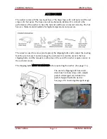
Page 14: ... higher temperatures and pressure The wrench is used to remove and replace the shipping bolts and to adjust the leveling feet Be sure to leave it and encourage the customer to retain the wrench the four shipping bolts and the manual in a safe place in the event the washer requires service or the customer moves The shipping bolts MUST BE REMOVED before operating the washer See page 13 The wrench sh...

Page 15: ...r right bolt is equipped with a clip that secures the cord so it is impossible to plug in the machine without removing the bolt The cord is further secured by an adhesive sticker which must be broken to free the cord to plug in the machine INSTALL THE WASHER ON A FIRM FLAT SURFACE ADJUST THE FEET TO BE LEVEL LOCK THE ADJUSTERS IN PLACE ...

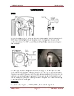
Page 16: ...RAIN The drain pipe should be firmly attached to the standpipe or the laundry tub or sink where it drains The pump has sufficient power to cause the pipe to move around when the water is expelled The pump can lift the drain water a maximum of 96 inches 2 4 m but there is no minimum height requirement The vacuum breaker in the drain line will prevent drainage by gravity or siphoning The hose can la...

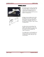
Page 17: ...e and instructions form the shipping carton Set the pedestal as close to the installation position as possible Level the pedestal on a flat solid floor before proceeding Lock down the rear adjusters but leave the front ones free for now Note which holes are for the washer and which are for the dryer If you are stacking the appliances the washer must be on the bottom Remove the protective paper fro...

Page 18: ...ed adhesive away from the appliance insert the screws and get them started Then press the brackets to the appliance and tighten all the screws Rub the bracket from side to side to ensure a complete bond Use the wrench to turn each leg of the appliance approximately turn to put a little pressure between the appliance and the pedestal This will eliminate any rattles and vibration It is usually easie...

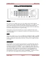
Page 19: ...l render every button except the POWER button CL blinks in the display when the CHILD LOCK is engaged To turn off the machine if it is running with CHILD LOCK engaged you must first disengage CHILD LOCK and then press POWER to turn it off The START PAUSE button is incorporated into the CYCLE SELECTOR knob Twist the knob to select a cycle push it to push it to START or PAUSE the cycle The CUSTOM PR...

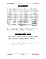
Page 20: ...de See the cycle and option chart on the following page BEFORE PERFORMING SERVICE Be careful to avoid electric shock when disconnecting parts for troubleshooting Most terminals in the steam washer have 120 Volts AC or DC on them sometimes even when the washer is off The steam generator operates at a high temperature Be careful when servicing it It can be drained in place by removing the drain cap ...

Page 21: ...TRAINING MANUAL WM0742HGA WM0742HGA Page 19 TRAINING MANUAL CYCLE and OPTION CHART See also the section covering PROCESS TECHNICAL INFORMATION on pages 89 and 90 of this training manual ...

Page 22: ...ed to every cycle except DELICATES HAND WASH WOOL and SPEED WASH It is locked out of these cycles to prevent damage to delicate clothing While the laundry is washing the steam generator boils water to spray steam through the laundry as it tumbles STEAM FRESH Steam Fresh is not an actual wash cycle Instead it is a cycle that tumbles up to five laundry items in a spray of steam to refresh the fabric...

Page 23: ...ine Just because an item can be forced into the tub is not evidence it can be successfully laundered there In every case the laundry must be able to tumble to be cleaned effectively If you push a king sized comforter into the tub but it is so compressed it cannot tumble it cannot be washed or rinsed effectively Further it will be unable to distribute itself within the drum for the spin cycle and w...

Page 24: ...evolution per tumble which is just enough to turn the load over in the water SPEED WASH SPEED WASH is the quickest cycle that provides a complete wash and rinse It defaults to a 0 35 minute cycle The default selections can be overridden for wash temperature spin speed and soil level very hot water and high speed spin but certain options cannot be selected If a selection is not permissible with the...

Page 25: ... is a cycle that reduces the spin speed after sensing an unbalanced load To engage the SPINSENSE press POWER and select a cycle Press and hold the SPINSENSE Rinse Spin button SPINSENSE will remain engaged until it is disengaged by the user Turning the machine off or losing power will not disable SPINSENSE CHILD LOCK CHILD LOCK is designed to disable the control pad after the cycle is started To ac...

Page 26: ...ump will operate throughout the tub clean cycle Near the end of the tub clean cycle the washer will pump out the water and spin at 960 rpm until the end of the cycle We recommend draining the water from the sump after running a tub clean cycle to ensure there are no residual cleaners or chemicals that might damage any subsequent load of laundry EXTRA RINSE The EXTRA RINSE cycle inserts a second ri...

Page 27: ...me out of the hot water faucet COLD was whatever came out of the cold water faucet and WARM was what happened with both valves opened The washing machine uses a thermistor and computer to regulate the water input adding hot or cold water as needed to adjust the temperature If the washer cannot achieve the desired temperature with the addition of hot water to the tub the heater will be activated an...

Page 28: ... chosen for a NORMAL cycle The prewash valve is opened and cold water is supplied briefly then the hot valve is opened and water fills the tub to the target water level This water never reaches the set point so the heater is energized When the water temperature reaches 122 F the heater is turned off A Prewash valve opens cold water is supplied B Hot valve opens to raise the water temperature to 12...

Page 29: ...TRAINING MANUAL WM0742HGA WM0742HGA Page 27 TRAINING MANUAL WIRING DIAGRAM ...

Page 30: ...re are two compartments for detergent You may use liquid detergent products in the main wash compartment However if you use a pre wash cycle and put liquid detergent into both compartments all the detergent will run into the pre wash cycle causing oversudsing follower by a wash cycle with no detergent To use the pre wash cycle you may use either liquid or powdered detergent but you MUST use a powd...

Page 31: ...e molasses that do not flow easily We recommend the RULE OF TWOS concerning laundry products Use no more than TWO TABLESPOONS of detergent in either the pre wash or the main wash cycles Use no more than TWO TEASPOONS of softener or bleach While some HE laundry detergents suggest the use of as much as 4 ounces per load this is entirely too much detergent It will leave detergent film on your clothes...

Page 32: ...TRAINING MANUAL WM0742HGA WM0742HGA Page 30 TRAINING MANUAL DISPENSER HOSE CONNECTIONS ...

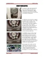
Page 33: ... than being attached to it A Hall Effect Sensor determines the speed and direction of the motor It also can read that the load is off balance when the drum speed fluctuates The Hall Effect sensor is easily removed and replaced You ll have to remove the rotor and stator to access the sensor When replacing the rotor the drum may move forward enough to make replacing the bolt difficult Carry a longer...

Page 34: ...ions for disassembly repair replacement of parts and re assembly Many times electrical components may be tested by connecting the appropriate meter to the leads or connectors on the main PC Board Refer to the block wiring diagram below Proper diagnosis will eliminate unnecessary labor and expedite repairs BLOCK WIRING DIAGRAM ...

Page 35: ...ws and take the board out of the control panel TOP COVER Open the dispenser lid and remove the 4 screws Take the lid assembly out of the top cover Release the plastic tabs that hold the dispenser assembly into the top cover Put your hand into the hole left by the dispenser and hold the top cover Use a putty knife or a thin blade to release the clip and lift the top cover Repeat the process on the ...

Page 36: ...arge hose attached to the dispenser When you replace it set it with the screw on top and the wing nut on the bottom for easier reach in the future Pull the large hose off the dispenser and remove the dispenser from the machine Unplug all the solenoids As with the hoses reconnection will be more convenient if you mark the connectors and valves now Remove the two screws at the back of the machine an...

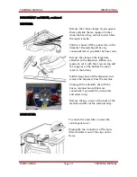
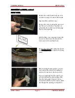
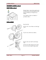
Page 37: ...he rim of the opening With the filter cover removed remove the two screws that secure the base of the front cover to the machine frame Remove the door gasket using the special tool 383EER4001A to remove the spring clamp After removing the door gasket you can reach inside the cabinet and unplug the electrical connector to the door switch If you are replacing the door switch you can do it without an...

Page 38: ... Be careful that the front does not fall forward causing injury or damage Set it aside face down on a blanket or protective surface DOOR and HINGE Open the door Remove the 7 screws that secure the hinge cover Pry the cover off with a screwdriver Remove the screws from the door hinge clips Lift the door off the hinge and set it aside Be sure to retain the plastic hinge shims ...

Page 39: ...wn the plastic tab on the base to slide the pump assembly backward This tab is for the convenience of the workers in the assembly plant It holds the pump in place while the machine is assembled If you break it don t worry about it The slot in the base and the two screws on the front will hold the pump securely in place You can tilt the pump in either direction to remove replace the individual pump...

Page 40: ... objects keys coins buttons etc that may find their way into the washer and protects the pumps from physical damage WASH HEATER Remove the front cover Disconnect the two electrical connections to the heater leads Disconnect the thermistor Remove the nut and ground wire on the heating element Loosen as far as possible but do not remove the second nut on the ground lug This will release the tension ...

Page 41: ...of the oscillator circuit of which it is a part As water level decreases frequency increases e g A low water level may read 25 5 kHz while a high water level may read 21 4 kHz These readings are approximate washers in the field may vary slightly from these figures To read the frequency while the WM0742 is running simultaneously press and hold the SOIL LEVEL and CUSTOM buttons The number on the dis...

Page 42: ... support it while you unplug two connectors on the stator Set the stator aside When re installing the stator the clamps and the ground screw must be installed and the connectors pressed into place before the rotor is bolted onto the shaft When you replace the rotor the shaft can be pressed forward so far the bolt will not reach it If you can t hold the tub back while you install the bolt get a lon...

Page 43: ...t See page 36 Disconnect all hoses and electrical connections Separate the three dampers See page 42 You can remove just one end now and the other end after the drum is out of the machine Pry apart the spring retainer clip Carefully lift the tub up off the springs and remove it from the machine Unbolt the bolts around the circumference of the seam Separate the halves Be careful to avoid damaging t...

Page 44: ... you can use a socket to hold the pin down while you press the pin out The color and or appearance of the damper may vary by model but the operation is the same Use special tool 383EER4003A to remove the damper pins If you are replacing the dampers you ll have to remove both ends If you are removing the tub for major repair work disconnect the damper ends at the base and leave the other ends conne...

Page 45: ...ine cabinet If you remove the steam generator before draining it be sure to avoid tipping it and spilling the water The steam generator can be removed as an assembly for diagnosis and replacement Unplug the washer Disconnect all electrical connections including ground Drain the water You can drain the water later and it is easier Remove all the cable straps by squeezing the tabs and pulling them o...

Page 46: ...e to the steam generator There is a check valve that fits into the input port The valve sometimes comes off and is stuck in the hose This could cause the water not to flow which would cause the steam generator to malfunction More recent models have a retainer built into the check valve to eliminate this issue Pull the check valve out of the hose gently and replace it into the water input port Then...

Page 47: ...The rear connector with black and white leads is the temperature sensing thermistor The center connector with a pink and white wire is the low water sensor The front connector with a single violet lead is the high water sensor From the wiring diagram you will see that the white wire NA is the GND reference The Pink wire is the low water sensor lead The violet lead is the high water sensor lead Low...

Page 48: ...uld activate the cold inlet valve for the steam generator before energizing the heater IF steam was selected and the control board wanted steam High Water Sensor Sensing Full In this picture we see the meter displaying less than 1 5 VDC In this example the water in the housing is touching the high water sensor probe and the ground probe When this occurs conductivity through the water is measured a...

Page 49: ... amperages If any component fails the steam generator must be replaced as an assembly The thermistor is a NTC Negative Temperature Coefficient device as temperature goes up resistance goes down The ohm value at room temperature is approximately 60KΩ and the voltage measured across the sensor is approximately 3 6 VDC At 212º the ohm value is approximately 3 3 KΩ and the voltage measured across the ...

Page 50: ...or wiring The error involves wiring terminal designation See the diagrams below The correct wiring terminal colors are White is Gray is Red is Hb Blue is Ha The correct depiction is shown left and the incorrect depiction is shown right Correct Incorrect Pay particular attention to the color codes and the position numbers in the connectors This will be critical when you take voltage readings to det...

Page 51: ... to 1 pulsing 10 VDC Signal Output 4 to 2 pulsing 10 VDC Signal Output Note Ohm values are approximate if the ohm check determines either resistor open the hall sensor has failed and must be replaced 1 BL Ha 2 RD Hb 3 Not Used 4 GRY 5 WH Hall Sensor testing methods are now available on the following pages when LE error code troubleshooting says hall sensor is out of order or defective Test FIRST ...

Page 52: ...d the rotor 4 Place the meter leads on terminals 5 to 4 white to gray 5 Plug in the power cord close the door and press the power button DO NOT PRESS START 6 You should measure 10 to 15 VDC If 10 to 15 VDC is present the control board is OK If not follow the testing output voltages on control board in next section 7 To measure output signal voltage from the hall sensor carefully move test leads to...

Page 53: ...y 10 to 15 VDC Gray to Blue pulsing 10 VDC Gray to Red pulsing 10 VDC Note If 10 VDC from gray to blue or gray to red does not change pulse that resistor is open Confirm by disconnecting the power disconnecting the hall sensor connector on the main board and ohm checking that individual circuit With power disconnected and the connector disconnected the hall sensor can be tested ohmmetrically from ...

Page 54: ... PRESS START 7 Place your meter leads on the WHITE and GRAY wires You should read between 10 15 VDC output from the main board to the hall sensor If 10 15 VDC are not observed the main board is defective 8 Place your meter leads on the BLUE and GRAY wires Turn the motor rotor slowly by hand You should measure a pulsing 10 VDC Place your meter leads on the RED and GRAY wires Turn the motor rotor sl...

Page 55: ...am valve Cold Water level freq 25 65 2 10 Tumble counterclockwise rpm1 42 50 11 Tub heater 1 2 seconds Water temperature tub C3 12 Circulation pump Water level freq 25 65 2 13 Drain pump Water level freq 25 65 2 14 Water level sensor steam Water level freq 31 246 2 15 Steam generator heater Water temperature TSG C3 16 Off Notes 1 Insert a zero at the end of the displayed numbers to determine the a...

Page 56: ...error code if the error is not cleared within 20 seconds the machine will be turned off automatically and the error code will blink on the display In the case of any other error code if the error is not cleared within 4 minutes the machine will be turned off automatically and the error code will blink on the display In the event of an FE error code the machine will be turned off and will not be re...

Page 57: ...TRAINING MANUAL WM0742HGA WM0742HGA Page 55 TRAINING MANUAL ERROR CODES continued ...

Page 58: ...TRAINING MANUAL WM0742HGA WM0742HGA Page 56 TRAINING MANUAL DIAGNOSIS and CHECK LIST Abnormal Operation NO POWER NO WATER INPUT ...

Page 59: ...TRAINING MANUAL WM0742HGA WM0742HGA Page 57 TRAINING MANUAL DIAGNOSIS and CHECK LIST Abnormal Operation continued DOOR ERROR DRAIN ERROR ...

Page 60: ...TRAINING MANUAL WM0742HGA WM0742HGA Page 58 TRAINING MANUAL DIAGNOSIS and CHECK LIST Abnormal Operation continued OVERSUDSING NO SOFTENING ERROR CODES ...

Page 61: ...TRAINING MANUAL WM0742HGA WM0742HGA Page 59 TRAINING MANUAL FAULT DIAGNOSIS and TROUBLESHOOTING NO POWER ...

Page 62: ...TRAINING MANUAL WM0742HGA WM0742HGA Page 60 TRAINING MANUAL DIAGNOSIS TROUBLESHOOOTING continued VIBRATION and NOISE IN SPIN CYCLE ...

Page 63: ...TRAINING MANUAL WM0742HGA WM0742HGA Page 61 TRAINING MANUAL DIAGNOSIS TROUBLESHOOOTING continued NO WATER SUPPLY DETERGENT FAILS TO DISPENSE ...

Page 64: ...TRAINING MANUAL WM0742HGA WM0742HGA Page 62 TRAINING MANUAL DIAGNOSIS TROUBLESHOOOTING continued LIQUID DETERGENT BLEACH SOFTENER FAIL TO DISPENSE ABNORMAL SOUND ...

Page 65: ...TRAINING MANUAL WM0742HGA WM0742HGA Page 63 TRAINING MANUAL DIAGNOSIS TROUBLESHOOOTING continued HEATING WITHOUT WATER DRAIN MALFUNCTION ...

Page 66: ...TRAINING MANUAL WM0742HGA WM0742HGA Page 64 TRAINING MANUAL DIAGNOSIS TROUBLESHOOOTING continued WASH HEATER MALFUNCTION WASH HEATER OVERRUN ...

Page 67: ...TRAINING MANUAL WM0742HGA WM0742HGA Page 65 TRAINING MANUAL DIAGNOSIS TROUBLESHOOOTING continued CIRCULATION FAILURE ...

Page 68: ...TRAINING MANUAL WM0742HGA WM0742HGA Page 66 TRAINING MANUAL DIAGNOSIS TROUBLESHOOOTING continued SPIN MOTOR MALFUNCTION dE ERROR CODE ...

Page 69: ...over the connections BAFFLES Lifters You can replace the baffle and rollers without having to remove the drum Unscrew the retaining screw at the back of the baffle Slide it toward the front of the washer to remove it You can unscrew the retainer inside the baffle to replace the roller balls MUSHROOM VALVE Be sure the mushroom is in place before attaching the hose If the stem is too long it will co...

Page 70: ...TRAINING MANUAL WM0742HGA WM0742HGA Page 68 TRAINING MANUAL MAIN BOARD ...

Page 71: ...TRAINING MANUAL WM0742HGA WM0742HGA Page 69 TRAINING MANUAL EXPLODED VIEW CABINET ASSEMBLY ...

Page 72: ...TRAINING MANUAL WM0742HGA WM0742HGA Page 70 TRAINING MANUAL DRUM and TUB ASSEMBLY ...

Page 73: ...TRAINING MANUAL WM0742HGA WM0742HGA Page 71 TRAINING MANUAL DISPENSER ASSEMBLY ...

Page 74: ...ong with cord clip X 1 A110 3457ER1002M Top Cover A125 3210ER1306A Frame Rear A130 3550ER0005E Front Cover Cabinet A131 AEJ33026601 Holder Assembly A133 ACA32390101 Clamp Outer Gasket Spring A136 3847ER3001A Name Plate Assembly A140 4775ER2001A Hinge Assembly A141 AEJ33026601 Holder Assembly A150 3581ER0001Q Door Assembly A151 3212ER0003B Frame Door Outer A152 3212ER1011A Frame Door Inner A153 365...

Page 75: ...2001A Bellows Dispenser to tub F315 4738ER2002A Bellows Tub to air vent F321 5214FR4125T Hose Inlet Cold to Main Wash F322 5214FR4125Q Hose Inlet Cold to Pre Wash F323 5214FR4125D Hose Inlet Cold to Bleach F324 5214FR4125P Hose Inlet Hot to Main Wash F326 5214FR4125R Hose Inlet Cold to Softener F327 5214FR4125Y Hose Cold to Steam Generator F328 5214FR4006Z Hose Recirculation Pump to Tub F430 5215E...

Page 76: ...or Recirculating Pump K346 383EER2001A Parts Assembly K350 4417EA1002H Stator Assembly K351 6501KW2002A Sensor Assembly K360 4413ER1003A Rotor Assembly K410 4970FR2084N Spring Hinge K411 4930FR3040A Holder K510 4986ER0001E Gasket K512 4932ER3007A Connector Nozzle K520 4738ER1002A Bellows K530 4861ER2001F Clamp Outer Gasket Spring K540 3504ER3002A Chamber Air K550 5214FR4125N Hose Tub to Pressure S...

Page 77: ...0742HGA WM0742HGA Page 75 TRAINING MANUAL Loc Part No Description 383EER4001A GASKET PLIER SPECIAL TOOL 383EER4003A DAMPER PLIER SPECIAL TOOL 383EER4004A GASKET PLIER SPECIAL TOOL 5214FR3018D DRAIN HOSE EXTENSION 5 FEET ...

Page 78: ...n change was made Some models may have four 4 letters instead of two 2 for the product code number The third and fourth letters are significant only to the manufacturing facility This chart will help you decode the serial number Example 801KW3400251 801 KW 00251 Production Number Internal code Manufactured January 2008 34 Made in Korea Newer Style With Barcode Sequential number Internal code Model...

Page 79: ...ms Watts Amperes2 x Ohms Watts Volts x Amperes I AMPERES Amperes Volts Ohms Amperes Watts Volts Amperes I R 2 E R 2 P R P I E I E R P E P R P I 2 E P 2 P E I I R I E R WATTS CURRENT VOLTS OHMS E VOLTS Volts Volts Watts Amperes Volts Amperes x Ohms R OHMS Ohms Volts Amperes Ohms Volts2 Watts Ohms Watts Amperes2 ...

Page 80: ... C Allergiene 140 F 60 C Hot 122 F 50 C Warm 104 F 40 C Cold 86 F 30 C Tap Cold whatever is in the pipe STAIN CYCLE Adds cycle time and increases wash temperature SPIN SPEEDS Extra High 1 150 rpm High 1 010 rpm Normal 1 000 rpm Low 960 rpm Gentle 400 rpm SOIL LEVEL Increases or decreases total cycle times wash and rinse Heavy 1 22 Normal 0 52 Low 0 47 ...

Page 81: ...TRAINING MANUAL WM0742HGA WM0742HGA Page 79 TRAINING MANUAL SERVICE BULLETINS ...

Page 82: ...TRAINING MANUAL WM0742HGA WM0742HGA Page 80 TRAINING MANUAL ...

Page 83: ...TRAINING MANUAL WM0742HGA WM0742HGA Page 81 TRAINING MANUAL ...

Page 84: ...TRAINING MANUAL WM0742HGA WM0742HGA Page 82 TRAINING MANUAL ...

Page 85: ...TRAINING MANUAL WM0742HGA WM0742HGA Page 83 TRAINING MANUAL ...

Page 86: ...TRAINING MANUAL WM0742HGA WM0742HGA Page 84 TRAINING MANUAL ...

Page 87: ...TRAINING MANUAL WM0742HGA WM0742HGA Page 85 TRAINING MANUAL ...

Page 88: ...TRAINING MANUAL WM0742HGA WM0742HGA Page 86 TRAINING MANUAL ...

Page 89: ...TRAINING MANUAL WM0742HGA WM0742HGA Page 87 TRAINING MANUAL ...

Page 90: ...TRAINING MANUAL WM0742HGA WM0742HGA Page 88 TRAINING MANUAL ...

Page 91: ... FUZZY LOGIC determines the wash time according to load size water temperature and other factors 6 Draining The drain pump drains the water from the sump Spin starts after the pressure switch indicated the water has been drained In cycles with hotter than usual water Allergiene and Sanitary cycles a cooling process is performed to lower the water temperature for safety and to avoid damaging the la...

Page 92: ... drum is rotated clockwise and counterclockwise to rinse the load 13 Final Draining After the rinse cycle is completed the power to the motor is cut off and the drum continues to spin by inertia until it stops If RINSE HOLD is selected the drum is not drained after the rinse cycle is completed 14 Detangling At the end of the cycle the power to the motor is cut off and the drum continues to spin by...

Page 93: ......

Page 94: ...Steam Washer Fall 2008 ...

Reviews: