background image

34

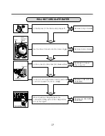
Open the door

.

Unscrew the 7 screws from the HINGE COVER

.

Put a flat ( - ) screwdr

i

ver 

i

nto the openng of the h

i

nge,

and pull out the h

i

nge cover

.

Unscrew a screw from the lower s

i

de of door

.

D

i

sassemble the door upward

.

Open the door and d

i

sassemble the CLAMP

ASSEMBLY

.

Unscrew the 2 screws

.

Be careful!

The door 

i

s heavy

.

NOTE 

 Reconnect the connector after replac

i

ng the

DOOR SWITCH ASSEMBLY

.

Summary of Contents for WM3997H*A

Page 1: ...WASHING MACHINE SERVICE MANUAL CAUTION READ THIS MANUAL CAREFULLY TO DIAGNOSE PROBLEMS CORRECTLY BEFORE SERVICING THE UNIT Website http biz lgservice com MODEL WM3997H A ...

Page 2: ...69 MFL67307985 o N P JULY 2012 PRINTED IN KOREA ...

Page 3: ... CONTENTS ...

Page 4: ...WARNING Wash hands after handling WM3997H A ...

Page 5: ...ke it possible to load and unload clothing more easily Steam Washing Steam washing features upgraded washing performance with low energy and water consumption RollerJets Washing ball enhances the wash performance and reduces damage to the clothing The jets spray and help tumble clothes to enhance washing performance while maintaining fabric care Automatic Wash Load Detection Automatically detects ...

Page 6: ...m then proceeds Spinning does not proceed until the water in the tub drains to a certain level water temperature washing time rinsing time the best washing performance spin rhythm time load size NEURO FUZZY selected washing temperature SENSING EFFECT PROCESSING DETERMINATION The door can be opened by pulling the door handle whenever washer is not in operation When the cycle is completed the DOOR L...

Page 7: ...ton for 3 seconds to lock unlock control When child lock is set CHILD LOCK lights and all buttons are disabled except the POWER button You can lock the controls of the washer while washing CHILD LOCK lasts after the end of cycle If you want to deactivate this function Press and hold the STAIN CARE button for 3 seconds 2 8 WATER CIRCULATION When washing and rinsing function of shower at the upper p...

Page 8: ...3 PARTS IDENTIFICATION Accessories ...

Page 9: ...r servicing operate the appliance to see whether it functions correctly STANDARD INSTALLATION The appliance should be installed as follows Remove the 4 shipping bolts with the supplied wrench Remove the lower boits fist It is easier that way Keep the shipping bolts and spanner for future use Insert the 4 caps provided into the hole Turn clockwise to raise counterclockwise to lower Turn the levelin...

Page 10: ... drips on the drawer panel handle and drawer panel HOW TO CONNECT THE INLET HOSE CONNECT THE DRAIN HOSE Make sure that the hose is not twisted CONNECT POWER PLUG The end of the drain hose should be placed less than 96 from the floor Avoid submerging the end of the hose Connect the power plug to the wall outlet Avoid connecting several electric devices as doing so may cause a fire Hot Cold ...

Page 11: ...Check if the drum rotates clockwise and counterclockwise 5 Check the automatic reverse rotation 4 Check the water supply Check if water is supplied through the detergent dispenser 7 Check the drain and spin functions Power off and the power on Press the SPIN SPEED button Press the START PAUSE button Check the spin and drain functions Listen for a click to determine if the door is unlocking 8 Press...

Page 12: ... F2004RDT ...

Page 13: ......

Page 14: ...ime Delay RINSE SPIN TEMP Button DRY SELECTOR 8BTI VUUPO ...

Page 15: ......

Page 16: ...17 7 TEST MODE SPIN SPEED SOIL LEVEL WASH RINSE DELAY WASH ...

Page 17: ...18 8 TROUBLESHOOTING ...

Page 18: ...S and 4 pin female white connector in the MAIN PWB ASSEMBLY is bad or unstable The MOTOR HARNESS between the STATOR ASSEMBLY and MAIN PWB ASSEMBLY is cut open circuited The hall sensor is out of order defective 8 EEPROM is out of order Displayed only when the START PAUSE button is first pressed in the Load Test Mode 9 g n i h s a w e l i h w d e p p o t s s i y l p p u s r e w o p e h t r e t f A ...

Page 19: ...re Check the fuse or reset the circuit breaker Replace the FILTER ASSEMBLY CIRC Replace MAIN PWB ASSEMBLY Reconnect Replace the MAIN PWB ASSEMBLY NO POWER 8 3 FAULT DIAGNOSIS AND TROUBLESHOOTING 1 Be careful of electric shock if disconnecting parts while troubleshooting 2 First of all check the connection of each electrical terminal with the wiring diagram 3 If you replace the MAIN PWB ASSEMBLY re...

Page 20: ...G G G G G G Gs G G G G G G U w G G G GO PG G G G GxjG G G G G G G Oy G G G TYPUG G G G G G G G S G G G G U piyh pvuGMGuvpzlGpuGzwpu p G G G G SG G G UGh G G G SG G G G G G G G G G G UGh G G G G U p G G G G G G G SG G U G U G GOYG GZG PG G UGv G S G SGy Rz G G G V G G U G G G G G G G S G G G G UG ...

Page 21: ...6 Press the Start Pause button 7 Press the Beeper button repeatedly to set spin speed 600 800 1000 1200 rpm and check if there is vibration and noise 8 If there is no vibration and noise increase the spin speed by pressing Beeper button 9 If there is vibration and noise rotate the Cycle selector knob clockwise to reduce the Spin Speed reduce by 50 and 100 rpm In case of 600 rpm it can not reduce t...

Page 22: ...23 5 4 Steam 5 4 Dry Steam Dry ...

Page 23: ...24 Softener cap ...

Page 24: ...25 HEATING WITHOUT WATER DRAIN MALFUNCTION ...

Page 25: ...s is s o o o o o zi yk yk is yk s ir ir o i z G G G G G G G U p G G GYYWG Ghjf w G olytpz vy G G G U G G G olytpz vy G G SG G G olytpz vy f HEATING CONTINUOUSLY ABOVE THE SETTING WATER TEMPERATURE WASH HEATER TROUBLE ...

Page 26: ...ATE WATER p G G G G G G G f h G Go Gj G V Go G f p G G G SG f p G G G G G G G G G G G G fGOj GyG GX_TZWG P G G G G G G G SG G G GYYW hjSG G G f y G G U y G G U y G G G G U y Gw twGtv vy hzzltis U y G Gthpu w i hzzltis U ...

Page 27: ...G UG G Gy SGz SG Gw G G G G G G SG G z hy Vwh zl GYG G GxjG G S G G G G G G f p G G SG G f y aGZ GOXPSGuhaG GOYP j G G G SGp G G G G G G G G G f tv vyG lytpuhs y G G aG h G G X G y G GthpuGw iGhzzltis k G G G Gs Go G f p G G G G G G G G z hy Vwh zl G G G G G G f p GkvvyGz p joGh8zzltis G f y Gk Gh U j G GkvvyGz p jo hzzltis Gj G thpuGw iGhzzltis Oy GZG SG G G G GZG G GOXPPU y G Gkvvy z p joGhzzlti...

Page 28: ... of thermistors on dry duct 2 5k 180k at 100 0 Clean the bellows Disassemble the cabinet cover and condensing bellows Is there any foreign object in the condensing bellows Disassemble the dry fan assembly and dry duct upper and remove foreign objects in duct and fan ...

Page 29: ...30 ...

Page 30: ...sconnect the Display PWB assembly connector from the cabling 4 Pull out the drawer and unscrew 2 screws 5 Remove one screw 6 Lift the side the control panel assembly and pull it out 7 Unscrew the 8 screws from the control panel assembly 8 Disassemble the display PWB assembly TOP PLATE ASSEMBLY CONTROL PANEL ASSEMBLY DRAWER CONTROL PANEL ASSEMBLY DISPLAY PWB ASSEMBLY 9 DISASSEMBLY INSTRUCTIONS ...

Page 31: ...AIN PWB ASSEMBLY Disconnect the POWER connector and the pressure switch assembly Remove the protective cover Unscrew 1 screw on the back Remove the main PWB Disconnect the connectors PROTECT COVER 1 2 3 4 5 ...

Page 32: ... G G G U k G G G G U w G G G U w G G GkpzwluzlyGhzzltis G GYG U G G G G G vwGiyhjrl U k G G G G Gwv ly jvykU Gj k G G G G G G U GYG G G G G G G U X Y Z 5 i Go GO sTirP y Go O TirP Go O oTirP i Go On TirP y Go OisTirP ...

Page 33: ...e openng of the hinge and pull out the hinge cover Unscrew a screw from the lower side of door Disassemble the door upward Open the door and disassemble the CLAMP ASSEMBLY Unscrew the 2 screws Be careful The door is heavy NOTE Reconnect the connector after replacing the DOOR SWITCH ASSEMBLY ...

Page 34: ...from upper of the cabinet cover Unscrew the screw from the filter cover Put a flat screwdriver or putty knife into the hinge slots at the bottom of the cover and pry it out Unscrew the screw from the lower side of the cabinet cover 1 2 3 4 ...

Page 35: ...embly Tilt the cabinet cover Disconnect the door switch connector Disassemble the clamp assembly Disassemble the gasket Lift and separate the cabinet cover NOTE When assembling the cabinet cover connect the door switch connector 5 6 7 8 9 10 11 ...

Page 36: ...the hinge Use the 8mm tool DOOR LOCK SWITCH ASSEMBLY Open the door and remove the gasket using the special gasket pliers Unscrew the 2 screws Disassemble the door upward NOTE Reconnect the connector after replacing the door switch assembly 1 3 1 2 2 ...

Page 37: ...onnectors from the heater Loosen the nut and pull out the heater THERMISTOR Disassemble the cabinet cover Unplug the white connector from the thermistor Pull it out by holding the bracket of the thermistor CAUTION When assembling the heater insert the heater into the heater clip on the bottom of the tub Tighten the fastening nut so the heater is secure CIRCULATION HOSE PUMP HOSE BELLOWS 1 2 3 1 2 ...

Page 38: ... heater from the tub Remove any foreign objects wire coin etc by inserting a long bar in the opening LAMP ASSEMBLY Unscrew 2 screws on the back of the top plate Pull the top plate backward and upward as shown TOP PLATE ASSEMBLY 1 2 3 1 Disconnect the connector 3 Disassemble the lamp assembly 4 2 ...

Page 39: ...hem they can be re used Bolt Rotor DAMPER HINGE DAMPER Disassemble the back cover Remove the bolt Pull out the rotor 1 2 3 Unscrew the 2 screws from the tub bracket Remove the 6 bolts on the stator Unplug the 2 connectors from the stator 1 2 3 Disassemble the damper hinges from the tub and base 1 ...

Page 40: ...485 A455 A410 A151 A130 A140 A131 A153 A390 A201 A440 A430 A100 A101 A104 A102 F215 F210 A450 A111 A110 A141 A150 A103 A220 A200 M410 A106 F110 A154 A152 8 EXPLODED VIEW 8 1 CABINET CONTROL PANEL ASSEMBLY 부 분해도 A175 A156 A180 A181 ...

Page 41: ... K411 K410 F463 K130 K530 F145 K340 F468 K135 F365 K611 K610 K360 K115 K141 K117 8 R M T B ASSEMBLY EXPLODED VIEW K571 K572 K570 F315 F465 K125 F464 F464 F310 K121 K122 K550 K540 F461 K520 K105 K190 K516 K346 K348 K344 K347 K349 K345 K342 43 K361 K513 K511 K142 ...

Page 42: ...F300 F327 F462 F225 F130 F120 F441 F430 F220 F226 F322 F323 F321 F180 Inlet Valve Filter SVC COLD BLUE HOT ORANGE 8 ISPENSER ASSEMBLY EXPLODED VIEW F170 F160 44 F432 F227 F340 F329 ...

Page 43: ...M110 M111 M215 M100 M130 M312 M310 K311 K311 M230 M220 M101 M240 M210 M311 M120 M121 M235 8 EXPLODED VIEW 45 ...

Reviews: