12
Function Mapping DCC
It is possible to assign functions controlled from the decoder to function buttons
of your choice (mapping). To do this an appropriate value must be entered in the
appropriate CV.
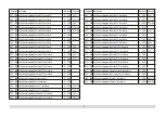
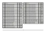
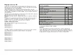
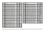
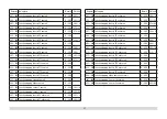
The CVs (lines) and the functions (columns) are listed in the tables on pages 40/41.
Four CVs belong to each button. For space reasons the 4 CVs were put together in
one line starting with CV 282 (Button F5).
It is basically possible to assign several functions to one button or one function to
several buttons.
Note:
The programming for function mapping should be done only by experienced
users.
Individual functions can be controlled by means of SUSI depending on the design of
the decoder. These functions can be handled by the decoder as sound. The volume
levels belonging to these functions
cannot
be changed.
Examples of Function Mapping:
AUX 2 is to be forwards and backwards on Function 3
CV 272 & CV 372 = 8
CV 273 & CV 373 = 0
CV 274 & CV 374 = 0
CV 275 & CV 375 = 0
Sound 15 is to be shifted from forwards and backwards on Function 3 to Function 8.
The existing function at Function 8 is overwritten in the process.
CV 275 & CV 375 = 0
CV 273 & CV 373 = 0
CV 274 & CV 374 = 0
CV 275 & CV 375 = 0
CV 297 & CV 397 = 0
CV 298 & CV 398 = 0
CV 299 & CV 399 = 0
CV 300 & CV 400 = 4
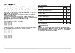
Controllable Functions
Lighting *
LV +LR
Sound effect: Long whistle blast
1
Sound 1
Sound effect: Squealing brakes off
2
BS
Sound effect: Short whistle blast
3
Sound 2
Sound effect: Bell
4
Sound 3
Sound effect: Operating sounds *
6
FS
Sound on/off
8
Sound 14
ABV, off
9
Engineer‘s cab lighting
10
AUX 3
Double A switching light
11
LV +LR
* active in analog operation
Note:
At www.LGB.de you will find a tool you can use to calculate different decoder set-
tings as well an extensive description of the decoder and the settings. Programming
the decoder settings with the 55015 Universal Hand Controller is also explained in
these instructions.


