background image

10

Safety Notes

•  This model may only be used with the operating system designed for it. 

•   Use only switched mode power supply units and transformers that are designed 

for your local power system. 

•  This locomotive must never be supplied with power from more than one power 

pack. 

•   Pay close attention to the safety notes in the instructions for your operating sys

-

tem.  

•  Not for children under the age of 15. 

•  

WARNING!

 Sharp edges and points required for operation. 

Important Notes

•   The operating instructions are a component part of the product and must therefore 

be kept in a safe place as well as included with the product, if the latter is given to 

someone else.

•   The warranty card included with this product specifies the warranty conditions.

•   Please see your authorized LGB dealer for repairs or spare parts.

•   The LEDs in this item correspond to Laser Class 1 according to Standard EN 60825-1.

•   Disposing: www.maerklin.com/en/imprint.html 

Functions 

•   This model is designed for operation on LGB two-rail DC systems with conventio

-

nal LGB DC train controllers or power packs (DC, 0 - 24 volts). 

•   Factory-installed multiple protocol decoder (DC, DCC, mfx).

•   The model is programmed with locomotive address 03 for use with the LGB Multi 

Train System (DCC). The locomotive is automatically recognized in operation with 

mfx. 

•   Mfx technology for the Mobile Station/Central Station.


Name set at the factory: 

F7A 5574

•   Volume can be changed for the sound effects 

•   The operating sounds are on in analog operation. 

•   The functions can be activated only in parallel. Serial activation of the functions is 

not possible (Please note here the instructions for your controller). 

Preparation

The rear brake cylinders on the front truck are not mounted on the model in order to 

guarantee trouble-free operation of this locomotive. The brake cylinders are included 

with the model. If the locomotive is only going to be used for display, then the brake 

cylinders can be installed. First, loosen the two screws on the side frame of the truck 

and remove the side frames. Then push the cylinders into the correct position. Put the 

side frames back on the model. 

Mode of Operation Switch

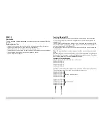
The model has a three-position mode of operation switch on the back wall (Figure 1):


Pos. 0  

locomotive stored without current 

Pos. 1  

everything on 

Pos. 2  

same as Pos. 1

Connection to the B Unit

On the back of the locomotive is a socket for connecting a B unit with a speaker. Only 

the 20588 B unit can be connected here. Connecting older B units or other cars will 

lead to damage. 

Important during Digital Operation!

If an A unit pointed in the opposite direction (example: the classic A-B-A locomotive 

combination) is coupled to this locomotive, then the direction of the second locomo

-

tive must be reprogrammed. Otherwise, the locomotives will run opposite to each 

other rather than in the same direction. To do this, program the register for CV 29 to 

Function Value 5 on the decoder built into the model at the factory (Please note here 

the instructions for your controller).

Sound

The bell and horn can be activated with the LGB sound activation magnet (17050) in

-

cluded with the locomotive. The activation magnet can be clipped into place between 

the ties of most LGB track sections. 

The magnet is positioned to the side under the LGB logo cast into the plastic cover. 

Place the magnet on one side to activate the horn when the locomotive passes over 

this spot. The bell will sound when the magnet is placed on the other side.

Multi-Protocol Operation 

Analog Operation

This decoder can also be operated on analog layouts or areas of track that are 

analog. The decoder recognizes alternating current (DC) and automatically adapts 

to the analog track voltage. All functions that were set under mfx or DCC for analog 

operation are active (see Digital Operation).

Digital Operation

The decoders are multi-protocol decoders. These decoders can be used under the 

following digital protocols: mfx or DCC.

The digital protocol with the most possibilities is the highest order digital protocol. 

The sequence of digital protocols in descending order is:

Priority 1: mfx; Priority 2: DCC; Priority 3: DC 

Summary of Contents for Rio Grande 20578

Page 1: ...Modell der DRGW Diesellok F7A 20579...

Page 2: ...2...

Page 3: ...CV 26 Tabel functiemapping DCC 40 Afbeeldingen 42 Onderdelen 44 Indice del contenuto Pagina Avvertenze per la sicurezza 34 Avvertenze importanti 34 Funzioni 34 Avvertenze per ilfunzionamento 34 Eserci...

Page 4: ...ell hat einen dreistufigen Betriebsarten Schalter an der R ckwand Abb 1 Pos 0 Lok stromlos abgestellt Pos 1 alles an Pos 2 wie Pos 1 Verbindung zur B Unit An der R ckseite der Lok ist eine Steckdose z...

Page 5: ...rden Es k nnen alle CV mehrfach gelesen und programmiert werden Die Programmierung kann entweder auf dem Haupt oder dem Programmiergleis erfolgen Die Defaulteinstellungen Werkseinstellungen k nnen wie...

Page 6: ...geh ren 4 CVs Aus Platzgr nden wurden ab CV 282 Taste F5 die 4 CVs zu jeder Taste jeweils in einer Zeile zusammengefasst Grunds tzlich ist es m glich einer Taste mehrere Funktionalit ten bzw eine Fun...

Page 7: ...Decoder kann unter DCC wahlweise ber die kurze CV 1 Adresse 1 127 oder die lange Adresse CV 17 CV 18 Adresse 1 10239 gesteuert werden Grunds tz lich sind immer beide Adressen belegt Mit CV 29 Bit 5 wi...

Page 8: ...er I 0 255 64 56 Motorregelung Regeleinfluss 0 255 24 CV Belegung Bereich Default 60 Multibahnhofsansage Bit 0 3 Anzahl der Bahnh fe Bit 4 Endansage wechselt die Reihenfolge Bit 5 Lokrichtung wechselt...

Page 9: ...r 1 vorw rts 0 255 348 16 352 355 Funktionsmapping Sensor 2 vorw rts 0 255 353 64 357 360 Funktionsmapping Funktion FL r ckw rts 0 255 357 49 362 365 Funktionsmapping Funktion F1 r ckw rts 0 255 363 1...

Page 10: ...rews on the side frame of the truck and remove the side frames Then push the cylinders into the correct position Put the side frames back on the model Mode of Operation Switch The model has a three po...

Page 11: ...n or also partially with the Mobile Station All of the Configuration Variables CV can be read and programmed repeatedly The programming can be done either on the main track or the programming track Th...

Page 12: ...our CVs belong to each button For space reasons the 4 CVs were put together in one line starting with CV 282 Button F5 It is basically possible to assign several functions to one button or one functio...

Page 13: ...means of a short CV 1 address 1 127 or a long address CV 17 CV 18 address 1 10239 Both addresses are basically always occupied CV 29 Bit 5 is used to determine which of the two addresses is currently...

Page 14: ...255 64 56 Motor control control influence 0 255 24 CV Assignment Range Default 60 Multi station announcement Bit 0 3 Number of stations Bit 4 Last announcement changes the sequence Bit 5 Locomotive di...

Page 15: ...or 1 forwards 0 255 348 16 352 355 Function mapping Sensor 2 forwards 0 255 353 64 357 360 Function mapping Function FL backwards 0 255 357 49 362 365 Function mapping Function F1 backwards 0 255 363...

Page 16: ...gie et d monter les cadres lat raux Monter ensuite les cylindres dans la bonne position Remonter les cadres lat raux Commutateur de mode d exploitation La maquette dispose d un commutateur de type d e...

Page 17: ...rogramm es par l interm diaire de la couche graphique de la station centrale voire en partie aussi au moyen de la station mobile Toutes les configurations variables CV peuvent tre lues et programm es...

Page 18: ...respondent 4 CV Pour des raisons de place les 4 CV correspondant chaque touche ont t regroup es sur une seule ligne partir de la CV 282 touche F5 En principe plusieurs fonctions peuvent tre affect es...

Page 19: ...dresse courte CV 1 adresse 1 127 ou l adresse longue CV 17 CV 18 adresse 1 10239 En principe les deux adresses sont toujours affect es La CV 29 Bit 5 permet de d finir l adresse valider Les param tres...

Page 20: ...u moteur param tre de r gulation I 0 255 64 56 R gulation du moteur influence de r gulation 0 255 24 CV Affectation Domaine Valeur par d faut 60 Annonce en gare multiple Bit 0 3 Nombre des gares Bit 4...

Page 21: ...vant 0 255 348 16 352 355 Mapping de fonctions Capteur 2 en avant 0 255 353 64 357 360 Mapping de fonctions fonction FL en arri re 0 255 357 49 362 365 Mapping de fonctions fonction F1 en arri re 0 25...

Page 22: ...rijfssoorten schakelaar Het model heeft een 3 standen bedrijfsschakelaar aan de achterwand afb 1 Pos 0 Locomotief stroomloos geparkeerd Pos 1 Alles aan Pos 2 Als Pos 1 Verbinding met B unit Aan de ach...

Page 23: ...nfiguratie variabelen CV kunnen vaker gelezen en geprogrammeerd worden De programmering kan zowel op het hoofdspoor als op het programmeerspoor gebeuren De default instellingen fabrieksinstelling kunn...

Page 24: ...e toets behoren 4 CV s vanwege plaatsgebrek worden vanaf CV 282 toets 5 de 4 CV s voor elke toets op n regel samengevat Het is in principe mogelijk om aan n toets meerdere functies dan wel een functie...

Page 25: ...pparaat met elkaar overeenkomen Lange adressen De decoder kan onder DCC na keuze via het korte CV 1 adres 1 127 of via het lange adres CV 17 CV 18 adres 1 10239 bestuurd worden In principe zijn beide...

Page 26: ...5 64 56 Motorregeling Regelinvloed 0 255 24 CV Belegging Bereik Default 60 Multi station omroep Bit 0 3 aantal stations Bit 4 eindstation omroep volgorde wijzigt Bit 5 rijrichting wijzigt de volgorde...

Page 27: ...1 vooruit 0 255 348 16 352 355 Functiemapping sensor 2 vooruit 0 255 353 64 357 360 Functiemapping functie FL achteruit 0 255 357 49 362 365 Functiemapping functie F1 achteruit 0 255 363 16 CV Beleggi...

Page 28: ...rantizar un funcionamiento sin problemas de esta locomotora no se han montado los cilindros de frenado posteriores del bogie delantero Se adjuntan los cilindros de frenado Si la locomotora se utiliza...

Page 29: ...n universalmente nica e inequ voca UID El decoder se da de alta autom ticamente en una Central Station o en una Mobile Station con su UID identificaci n Programaci n Las caracter sticas pueden program...

Page 30: ...nas Cada tecla tiene asociadas 4 CVs Por motivos de espacio a partir de la variable CV 282 tecla F5 se han agrupado en una sola l nea las 4 CVs asignadas a cada tecla Por norma es posible asignar a un...

Page 31: ...DCC el decoder se puede controlar mediante la direcci n corta CV 1 direcci n 1 127 o mediante la direcci n larga CV 17 y CV 18 direcci n 1 10239 Por norma ambas direcciones est n siempre asignadas Con...

Page 32: ...de regulaci n I 0 255 64 56 Regulaci n de motor factor de regulaci n 0 255 24 CV Configuraci n Rango Valor por defecto 60 Locuci n multiestaci n Bit 0 3 N mero de estaciones Bit 4 La locuci n final ca...

Page 33: ...o de funci n de marcha hacia delante 0 255 347 350 Mapeado de funci n Sensor 1 hacia delante 0 255 348 16 352 355 Mapeado de funci n Sensor 2 hacia delante 0 255 353 64 CV Configuraci n Rango Valor po...

Page 34: ...sono venire montati Svitare dapprima entrambe le viti sui telai laterali del carrello e rimuovere i telai laterali Fare scorrere poi i cilindri nella corret ta posizione Montare nuovamente i telai lat...

Page 35: ...he possono venire programmate tramite la superficie grafica della Central Station o rispettivamente in parte anche con la Mobile Station Tutte le Variabili di Configurazione CV possono venire ripetuta...

Page 36: ...tasto appartengono 4 CV Per ragioni di spazio a partire dalla CV 282 tasto F5 le 4 CV di ciascun tasto sono state rispettivamente raccolte assieme in una sola riga Essenzialmente possibile attribuire...

Page 37: ...zzo lungo Il Decoder pu venire comandato sotto DCC a piacere tramite l indirizzo breve CV 1 indirizzi 1 127 oppure l indirizzo lungo CV 17 CV 18 indirizzi 1 10239 Sostan zialmente entrambi gli indiriz...

Page 38: ...di regolaz I 0 255 64 56 Regolazione motore influenza sulla regolaz 0 255 24 CV Assegnazione Campo Default 60 Annunci di stazione multipli Bit 0 3 numero delle stazioni Bit 4 annuncio finale commuta...

Page 39: ...Mappatura funzioni sensore 1 in avanti 0 255 348 16 352 355 Mappatura funzioni sensore 2 in avanti 0 255 353 64 357 360 Mappatura funzioni Funzione FL indietro 0 255 357 49 362 365 Mappatura funzioni...

Page 40: ...4 2 1 128 64 32 16 8 4 2 1 292 295 F7 128 64 32 16 8 4 2 1 128 64 32 16 8 4 2 1 128 64 32 16 8 4 2 1 128 64 32 16 8 4 2 1 297 300 F8 128 64 32 16 8 4 2 1 128 64 32 16 8 4 2 1 128 64 32 16 8 4 2 1 128...

Page 41: ...4 32 16 8 4 2 1 128 64 32 16 8 4 2 1 128 64 32 16 8 4 2 1 128 64 32 16 8 4 2 1 397 400 F8 128 64 32 16 8 4 2 1 128 64 32 16 8 4 2 1 128 64 32 16 8 4 2 1 128 64 32 16 8 4 2 1 402 405 F9 128 64 32 16 8...

Page 42: ...h General Purpose Socket Img 1 2 Commutateur de mode d exploitation douille usage multiple Afb 1 2 Bedrijfsschakelaar universele stekkerbus Fig 1 2 Selector de modo de funcionamiento y enchufe multius...

Page 43: ...43...

Page 44: ...44 1 2 21 4 2 2 3 3 20 21 21 24 21 3 Details der Darstellung k nnen von dem Modell abweichen...

Page 45: ...45 20 24 6 24 7 8 3 7 26 26 24 24 24 26 24 24 21 20 21 21 21 21 23 21 21 25 7 7 7 9 9 5 Details der Darstellung k nnen von dem Modell abweichen...

Page 46: ...46 20 15 16 11 16 15 12 28 12 13 13 14 14 20 20 21 21 22 22 22 21 20 20 20 17 17 14 20 17 28 21 21 21 21 21 21 18 19 13 13 27 20 27 27 10 27 Details der Darstellung k nnen von dem Modell abweichen...

Page 47: ...17 Radsatz E142 325 18 Radsatz E142 327 19 Haftreifen E126 174 20 Schraube E124 010 21 Schraube E124 197 22 Schraube E129 265 23 Beilagscheibe E159 879 24 Schraube E124 014 25 Schraube E124 205 26 Bei...

Page 48: ...iance and an adjustment if necessary Use in the USA without this certification is not permitted and absolves us of any liability If you should want such certification to be done please contact us also...

Reviews: