MT86H
Operation
and
Maintenance
Manual
104
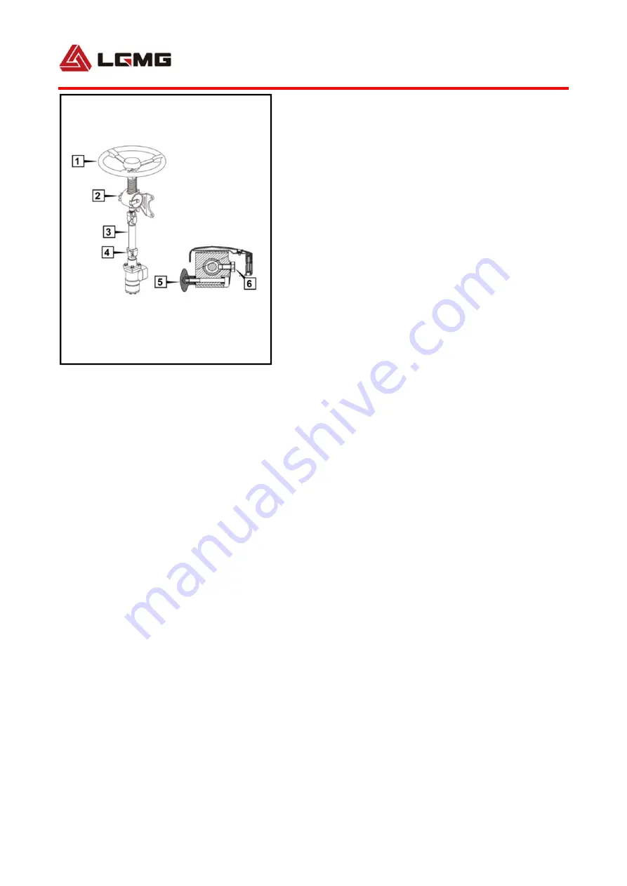
Fig 4‐35 Structure Diagram of Steering System
Operating Device
1. Steering wheel 2. Steering column
3. Steering drive axle 4. Universal joint
5. Regulating handle 6. Travel limit screw
operating
position,
and
tighten
the
adjusting
handle
.
4.7.2
Hydraulic
power
steering
system
Full-hydraulic steering gear, pilot valve,
hydraulic oil pump, hydraulic oil tank,
steering cylinder, hydraulic pipeline, etc.
The steering cylinder is φ70.
1) Full-hydraulic steering system
construction (as shown in Figure 4-33)
2) Full-hydraulic steering system principle
The steering pump is a vane pump. The engine
is directly connected with a power takeoff at
the position of engine power take off, and
keeps running. The steering pump sucks oil from
the hydraulic oil tank and outputs
high-pressure oil to a pilot valve P opening.
The pilot valve has following 5 openings: P,
EF, CF, and Ls. Excessive hydraulic oil of the
steering system returns to the oil tank via EF
opening. CF opening is connected with
full-hydraulic steering gear P opening to
provide high-pressure oil to the steering gear.
Ls opening is connected with steering gear Ls
opening as a control line. When the steering
wheel drives the steering gear to rotate, the
steering gear Ls opening provides a pressure
signal to the pilot valve Ls opening to enable
Summary of Contents for MT86H
Page 9: ...MT86H Operation and Maintenance Manual 1 Chapter I Safety ...
Page 10: ...MT86H Operation and Maintenance Manual 2 ...
Page 18: ...MT86H Operation and Maintenance Manual 10 ...
Page 19: ...MT86H Operation and Maintenance Manual 11 Chapter II Product Introduction ...
Page 20: ...MT86H Operation and Maintenance Manual 12 ...
Page 25: ...MT86H Operation and Maintenance Manual 17 Chapter III Operation ...
Page 26: ...MT86H Operation and Maintenance Manual 18 ...
Page 64: ...MT86H Operation and Maintenance Manual 56 ...
Page 142: ...MT86H Operation and Maintenance Manual 134 ...
Page 143: ...MT86H Operation and Maintenance Manual 135 Chapter V Maintenance ...
Page 144: ...MT86H Operation and Maintenance Manual 136 ...
Page 160: ...MT86H Operation and Maintenance Manual 152 3 Lubrication diagram ...
Page 161: ...MT86H Operation and Maintenance Manual 153 Chapter VI Annex ...
Page 165: ...157 6 5 Schematic diagram of electrical system ...


