○ ○ ○ ○ ○ ○ ○ ○ ○ ○ ○ ○ ○ ○ ○ ○ ○ ○ ○ ○ ○ ○ ○ ○ ○ ○ ○ ○ ○ ○ ○ ○ ○ ○ ○ ○ ○ ○ ○ ○ ○ ○ ○ ○ ○ ○ ○ ○ ○ ○ ○ ○ ○ ○ ○ ○ ○ ○ ○ ○
LI-COR Temperature Sensors
Operation and Installation Instructions
●
1400-101 (Replaces 1000-16)
●
1400-102 (Replaces 1000-16-2)
●
1400-103 (Replaces 1000-15)
Required Accessories
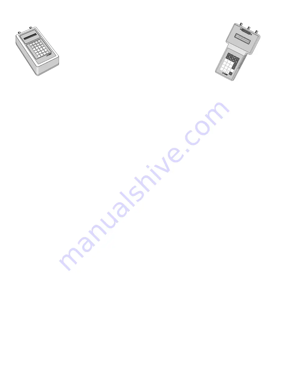
The 1400-101 Air Temperature Sensor, the 1400-102 Air Temperature Sensor, and the 1400-103 Soil Temperature Sensor can be used
with either the LI-1000 or LI-1400 Datalogger. Each of these sensors require either the 1000-05 Terminal Block, the 1000-06A AC
Terminal Block, 1000-10 Thermocouple Terminal Block or the 1400-301 Terminal Block. These sensors are not suitable for use with
the 1000-06 AC Terminal Block (purchased before April 15, 1987).
Connecting the Temperature Sensors
Each sensor is terminated with 3 wires which connect to the terminal block. The red lead also has a 33.2K ohm precision resistor connected
in series with the thermistor. The red lead is connected to the current input terminal for the channel being used. The black lead is con-
nected to the reg5 volt power supply, which is terminal C-9 on the 1000-05, C-9 on the 1000-06A, P1-3 on the 1000-10 or 5VDC
terminal on the 1400-301. The silver shield wire is connected to a signal ground terminal on the current channel in use.
1400-103 Installation.
The soil temperature sensor is designed to be as small as possible to facilitate burial at any desired depth.
However, when burying the sensor at shallow depths (< 10 cm) there are some practical considerations which should be observed. At
depths less than 10 cm it is much easier for the sensor to be accidentally pulled out or to be uncovered by strong winds. This can
usually be prevented by burying not just the tip of the sensor but a length of the cable as well. It is also best to bury the sensor and the
cable at an angle to the soil surface (not perpendicular). If using the 1000-08 or 1400-201 Instrument Enclosure, the cable can be run
up through the bottom of the enclosure and connected to the LI-1000 or LI-1400.
1400-102 Installation.
The 1400-102 air temperature sensor mounts in a hole in the bottom of the 1000-08 or 1400-201 Instrument
Enclosure and is held in place by two mounting collars which slide along the shaft of the temperature sensor. Take off one of the
collars and put the temperature sensor through the hole in the bottom of the enclosure. Replace the collar so that one is on either side
of the bottom of the instrument enclosure, and the tip of the air temperature sensor is one inch from the bottom of enclosure. In this
position the sensor will be correctly shaded by the shade ring and will still have good air circulation around it.
NOTE
: If the air
temperature sensor is installed in an older instrument enclosure (1000-08), the hole needs to be drilled out with a 0.5 inch drill bit so
the narrow end of the collars fit into the hole.
LI-1400 Configuration
The LI-1400 uses the Steinhart-Hart Equation to calculate temperature from LI-COR’s 1400-101, 102, and 103 temperature sensors.
Only a single set of coefficients is necessary and is preprogrammed into the LI-1400. When configuring a channel, select
Math=MLTHMSTR in the channel setup for any of these LI-COR temperature sensors.
LI-1000 Configuration
LI-COR temperature sensors are manufactured using non-linear thermistors. They are calibrated by calculating a polynomial to fit its
response curve. The calibration polynomial in the LI-1000 is of the form
Y = a0 + (a1)X + (a2)X2 + (a3)X3 + (a4)X4 + (a5)X5
where Y is the output of the thermistor in degrees Celsius; a0 through a5 are polynomial coefficients for the thermistor, and X is the
uncalibrated output of the thermistor. The calibration coefficients a0 through a5 are entered in memory in CONFIGURATION mode.
(over)
LI-10
00
Da
taL
og
ger
Fct
On/Off
Setup
Enter
7
4
1
0
8
9
5
6
2
3
Esc
EEX
View
Shift
M
P
T
X
Y
Z
V
U
R
Q
N
O
J
S
W
I
L
H
G
K
C
F
B
E
A
D
data
LO
G
G
ER
LI-1400
model
Ana
log
I/O


