background image

Section 3

3-20

Operation

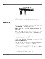
25-pin RS-232C Port

13 12 11 10 9

8

7

6

5

4

3

2

1

25 24 23 22 21 20 19 18 17 16 15 14

Jumper

610-03

black

red

black

red

LI-610

Figure 3-3.  Connection of the 610-03 and LI-610 to the LI-6200 25-pin
RS-232C port (shown connected to spare input channels 1 and 2).

References

Buck, A.L.  1981.  New equations for computing vapor pressure and
enhancement factor.  J. Appl. Meteor. 20: 1527-1532.

Goff, J.A., and S. Gratch.  1946.  Trans. Amer. Soc. Heat. and Vent. Eng.,
Vol. 52, p. 95.

Hyland, R.W.  1975.  A correlation for the second interaction virial
coefficients and enhancement factors for moist air.  J. Natl. Bur. Stand.,
79A, 551-560.

LI-COR, inc.  1990.  LI-6262 CO

2

/H

2

O Analyzer: Instruction Manual.

Publication No. 9003-59.  LI-COR, inc.

List, R.J.  1966.  Smithsonian Meteorological Tables, 6th rev. ed.  The
Smithsonian Institution, 527 pp.

Lowe, P.R.  1977.  An approximating polynomial for the computation of
saturation vapor pressure.  J. Appl. Meteorol. 16:100-103.

McDermitt, D.K., 1990.  Sources of error in the estimation of stomatal
conductance and transpiration from porometer data.  HortScience 25(12):
1538-1548.

Wexler, A.  1976.  Vapor pressure formulation for water in the range 0° to
100° C.  J. Res. Natl. Bur. Stand., 80A, pp. 775 ff.

Summary of Contents for LI-610

Page 1: ...LI 610 Portable Dew Point Generator Instruction Manual...

Page 2: ...LI 610 Portable Dew Point Generator Operating and Service Manual...

Page 3: ...nslated to another language without prior written consent of LI COR Inc Copyright 1991 LI COR Inc Printing History New editions of this manual will incorporate all material since the previous editions...

Page 4: ...ser Block 2 3 Power On 2 4 Section III OPERATION General Description 3 1 Air Flow Through the LI 610 3 1 Water Flow In the LI 610 3 2 Operation 3 3 Command Input 3 4 Analog Output 3 4 Theory of Operat...

Page 5: ...librating the LI 7500 CO2 H2O Infrared Gas Analyzer 4 12 Preliminary 4 12 Zero CO2 4 14 Zero H2O 4 14 Span CO2 4 14 Span H2O 4 15 Calibrating the LI 840 CO2 H2O Infrared Gas Analyzer 4 16 Calibrating...

Page 6: ...lock 5 1 Radiator Assembly 5 2 Internal Air Filter 5 2 Internal Water Filter Screen 5 3 External Fan Filter 5 4 Cleaning the Condenser Block 5 4 Fuses 5 5 Replacing the Air Pump Diaphragm 5 5 Rechargi...

Page 7: ...ing the radiator assembly Syringe A plastic syringe is included to facilitate filling and draining of the condenser block in the LI 610 Refer to Sections 2 and 5 respectively for complete filling and...

Page 8: ...is required if you wish to use the Analog Output and Command Input functions simultaneously 6200B Rechargeable Battery 10 5 16 VDC The 6200B Recharge able Battery is tested and fully charged before it...

Page 9: ...y Turn the power switch ON Turn the COOLER switch ON moment arily to flow water through the water pump and radiator assemblies Shut the LI 610 off and continue to fill the reservoir in this manner unt...

Page 10: ...lene glycol water will protect the radiator from freezing to approximately 40 C Ethylene glycol is the recommended antifreeze do not use propylene glycol or other antifreeze mixtures Radiator Fill Fig...

Page 11: ...25 20 15 10 5 Syringe Female Luer Lock Bev a line Tubing Male Luer Lock Thread a female Luer lock included in the spare parts kit into the syringe and draw 20 25 ml of water into the syringe Attach a...

Page 12: ...nse out of the input air stream thereby raising the water level in the condenser or evaporate out of the condenser into the output air stream lowering the condenser water level The condenser water may...

Page 13: ...the battery voltage reaches approximately 10 volts The Peltier coolers liquid pump air pump fan and display will turn off to conserve power The LI 610 should be turned OFF to prevent further battery d...

Page 14: ...ssembly When the AIR PUMP is switched ON and the FLOW ADJUST VALVE is opened the LI 610 will begin to generate an airstream with a dew point temperature equal to the condenser temperature established...

Page 15: ...R IN fitting on the instrument back panel Any impurities are removed from this air stream by a filter before it reaches the air pump Air leaving the pump passes through a flow adjust valve on the inst...

Page 16: ...or liberate heat depending upon the direction of electrical current flow through the junction of dissimilar metals When the coolers are switched ON current flows in a direction which causes heat to b...

Page 17: ...you to get close to the desired set point very quickly The FINE temperature adjustment knob is then used to set the dew point precisely 3 Set the function switch to the TEMP C position and turn the C...

Page 18: ...is required for an error 0 1 NOTE The LI COR LI 6400 Portable Photosynthesis System can be configured to provide an analog output channel that controls the dew point temperature of the LI 610 If both...

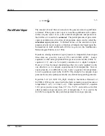
Page 19: ...essure of gas component i kPa V is volume m3 ni is the number of moles of gas component i R is the universal gas constant 0 008314 m3 kPa mol 1 K 1 and T is absolute temperature K Dalton s Law of part...

Page 20: ...a are given by Lowe 1976 and LI COR 1990 Lowe s equation is a 6th order polynomial that gives accurate results Table 3 1 equation 3 11 and can be rapidly calculated on a digital computer However it ha...

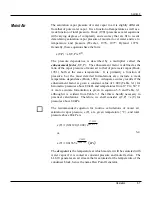
Page 21: ...but the most detailed formulations also include a weak temperature dependence Buck 1981 Adequate accuracy results if the enhancement factor is given a constant value of 1 004 Table 3 1 for barometric...

Page 22: ...C and P 105 kPa f T P 1 0041 a negligible difference It is apparent from equation 3 5 that the enhancement factor temperature and pressure dependence causes only small deviations from the nominal val...

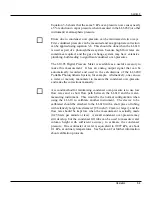
Page 23: ...table Photosynthesis System for example Alternatively one can use a water or mercury manometer to measure the condenser over pressure and make the corrections manually A second method for minimizing c...

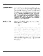
Page 24: ...r pressure Therefore no vapor pressure corrections are necessary for temperature differences that might occur in the system Relative Humidity Calibration of relative humidity sensors is a principal us...

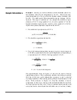
Page 25: ...ure must be 40 e 2 82 kPa 100 e 1 128 kPa 3 The LI 610 setpoint temperature necessary to give a vapor pressure of 1 128 kPa is equivalent to the dew point temperature corresponding to a vapor pressure...

Page 26: ...s before however the pressure correction from equation 3 6 must be inserted at step 3 before proceeding 1 e 23 2 820 kPa 2 The required chamber vapor pressure e 1 128 kPa 3 The LI 610 vapor pressure r...

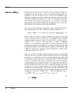
Page 27: ...lving for device temperature T 240 97 ln R f T 17 502 ln R f T d d 3 9 where T the pressure corrected dew point temperature in the measuring device given the LI 610 dew point temperature setpoint Td R...

Page 28: ...5 10 15 20 25 30 35 40 45 50 Temperature C 0 12 365 0 50 Relative Humidity Vapor Pressure kPa Air Temp T Vapor Pressure at T 40 RH Saturation Vapor Pressure at T Dewpoint Temp T 100 40 0 air DP DP air...

Page 29: ...051 0 126 0 287 0 611 1 226 2 334 4 238 7 378 12 365 39 85 29 93 19 97 10 00 0 00 10 00 20 01 30 01 40 01 49 98 39 96 29 98 19 99 10 00 0 00 10 00 20 00 30 01 40 01 50 02 39 88 29 93 19 95 9 95 0 06 1...

Page 30: ...ld ordinarily select the 0 l button 3 Attach a male Luer lock in the LI 610 spares kit to the fill drain port on the LI 610 condenser housing Connect a section of the 1 8 ID tubing included between th...

Page 31: ...00 mbar 1 mbar resolution Low 0 to 199 9 mbar 0 1 mbar resolution Accuracy 0 15 1 digit at 25 C Operating Range 10 to 50 C Temperature Effect 0 02 C 10 to 50 C Pressure Connections Two ports for 1 8 I...

Page 32: ...nector with the configuration shown in Figure 3 3 Connect the LI 610 red lead to pin 9 and the black lead to pin 10 connect the 610 03 red lead to pin 11 and the black lead to pin 12 Use a jumper to c...

Page 33: ...te saturation vapor pressure at the dew point temperature and finally correct for pressure It is not necessary to convert the 610 03 input voltage to pressure because the correspondence is already one...

Page 34: ...A correlation for the second interaction virial coefficients and enhancement factors for moist air J Natl Bur Stand 79A 551 560 LI COR inc 1990 LI 6262 CO2 H2O Analyzer Instruction Manual Publication...

Page 35: ...ns Scientist Dayle McDermitt HortScience Dec 1990 discusses a variety of topics concerning stomatal control of leaf conductance including the effects of sensor or calibration errors on the accuracy of...

Page 36: ...option B splitting the flow and connecting both the reference and sample with Match Off The reason for this is that you will be able to drastically reduce the equilibrium time waiting for the sample...

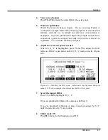
Page 37: ...he reference to equilibrate 3 to 5 minutes should be adequate 6 Adjust the reference gain as needed When Td_R_ C is highlighted press and to adjust the H2O reference IRGA s span factor until Td_R_ C r...

Page 38: ...se a dew point temperature that is about 3 to 5 C below the ambient temperature Also since water vapor sorbs and desorbs from surfaces allow plenty of time for the reading to stabilize and minimize th...

Page 39: ...action For the next 4 or 5 seconds the LI 7000 will average the readings it is taking then perform the requested action There are three major choices for calibration actions 1 Make cell A read 2 Make...

Page 40: ...do this while in REM NOTE You can use any concentration in the B cell to do this even 0 just make sure that there is a significant difference between the cell A and B concentrations Calibration Instru...

Page 41: ...l A Is Known but not Constant If during operation cell A will have a range of known concentrations a potential problem with common mode drift arises This can be minimized by adding a 2 Point Match to...

Page 42: ...odically Calibrate Cell A initially and periodically thereafter The cell A calibration Box 4 below is critical to how REM works After that experience will tell you how often it needs to be redone the...

Page 43: ...t Match The two point match will match the cells at a low and a high concentration The low concentration should be 20 mol mol for CO2 3 mmol mol for H2O the high concentration should be near the upper...

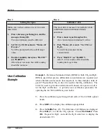
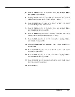
Page 44: ...r DoH2O After 5 or 6 seconds cell A should be reading the target value User Calibration Example Example 1 Reference Estimation Mode REM for both CO2 and H2O REM is used when precise differential conce...

Page 45: ...atch cell A and press OK 8 Press the DoH2O key f3 and wait for about 5 seconds The cell B reading will be matched to the H2O value of cell A 9 Press the Calib key f4 In the CO2 Actions box highlight M...

Page 46: ...be done separately In general if reliable calibration standards are not available or if there is not enough time to do the job properly it is better to leave the zero and span settings alone than to r...

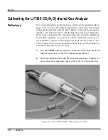
Page 47: ...forth until the AGC value reads the same value as before the fixture was inserted The fixture is very easy to center if it looks centered it probably is NOTE The three ports on the calibration tube ar...

Page 48: ...resultant value of Zco shown on the Zero CO2 page Figure 4 5 It should be near 1 typically between 0 85 and 1 1 This value will steadily increase as the internal chemicals lose effectiveness Zero H2O...

Page 49: ...ough the calibration tube at about 0 5 to 1 0 LPM To avoid condensation use a dew point temperature several degrees below the ambient temperature 14 Click the H2O tab and note the present value of Sw...

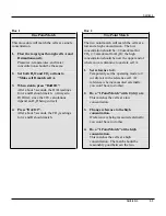
Page 50: ...span calibrations To zero flow a dry CO2 free gas through the LI 840 and make sure the optical cell is completely purged Press the Zero CO2 button The display will show ZERO and the text in the Calibr...

Page 51: ...t high accuracy is desired so they have long equilibration times Experience with CO2 analyzers causes one to expect rapid and stable responses to changes in gas concentration however this will not be...

Page 52: ...cells then reduce the flow rate in both cells to 0 25 liters min 1 for 10 to 20 minutes prior to setting zero Set zero Absolute Mode H20 Span Calibration 1 Set the LI 610 to a dew point corresponding...

Page 53: ...midities 1 Set zero and span in Absolute Mode as described above 2 Flow a reference gas through both the reference cell and sample cell for 20 min at about 1 liter min 1 Reduce the flow to 0 25 liters...

Page 54: ...the same flow rate as measurements whenever possible Further the calculations in the LI 6262 use the same pressure for both sample and reference cells Therefore flow rates and total pressures should...

Page 55: ...erture cap with the solid calibration cap included with the 610 02 RH Calibration Accessories kit Alternatively a sheet of non porous non water absorbing material can be clamped over the aperture Clos...

Page 56: ...play reads zero adjust the potentiometer until the display shows a small positive number and then turn the potentiometer down until the display reads zero and the null meter is centered Calibration Se...

Page 57: ...cm of water at a barometric pressure of 100 kPa then equation 4 1 becomes RH e e c 1 403 1 5853 0 997 100 83 1 Check Intermediate Values Conduct the following procedures without further adjustment to...

Page 58: ...ort lines and then remove the chamber from the sensor housing BE VERY CAREFUL NOT TO TOUCH SCRATCH OR SMOKE NEAR THE EXPOSED HUMIDITY SENSOR 3 Check to be sure that the sensors and the exposed parts o...

Page 59: ...tiometers in the LI 6200 or LI 6000 sensor housing as shown in Figure 4 7 below RH ZERO RH GAIN Figure 4 7 Location of the zero and span potentiometers in the LI 6200 or LI 6000 sensor housing 6 Disco...

Page 60: ...dependent condenser pressure as P 0 0979 kPa cm 1 water column height in cm This pressure factor will be used later 2 For the LI 6200 the humidity lookup table FCT 47 should match the values given on...

Page 61: ...Td 5 Compute the exact RH to which the span should be set This can be done using equation 4 1 A pressure correction must be applied when the vapor pressure is established in the dew point generator co...

Page 62: ...there is a deviation of greater than 3 RH If the intermediate RH deviations are too large when the zero and span are set correctly you may wish to make adjustments to the LI 6200 RH Calibration Table...

Page 63: ...ibration for a relative humidity sensor Follow the manufacturer s recommendations for making any adjustments i e potentiometers necessary for calibrating your particular humidity sensor Calibrating De...

Page 64: ...a female Luer lock included to the male Luer lock on the condenser block housing Thread the female Luer lock into the 30 ml syringe Use the syringe to draw the water out of the condenser block The bl...

Page 65: ...pend upon the operating environment it will generally need replacement after 6 months to 1 year The filter is located inside the LI 610 on the hose leading from the AIR IN fitting as shown in Figure 5...

Page 66: ...fitting Figure 5 1 This screen should be checked monthly as a clogged screen can severely limit the flow of cooling water through the system To clean the internal water filter screen Remove the cover...

Page 67: ...red at the TO CONDENSER port with the 610 03 Digital Pressure Meter If the pump appears to be functioning normally you may need to clean the condenser block with a solution of 1N acetic acid To clean...

Page 68: ...the holder on the back panel protects the 10 5 16 VDC battery circuit The 1 amp slow blow fuse protects the 610 01 AC Module that is used with 100 130 200 260 VAC line voltage If the LI 610 fails to t...

Page 69: ...he edge of the new diaphragm Connecting Rod Diaphragm Move the connecting rod to the bottom of its stroke and hold it while installing the new diaphragm The diaphragm must be properly centered by the...

Page 70: ...y of the batteries connected to the charger are being charged One method for testing a battery s charge is to connect it by itself into the charger If it is charged the CHARGE light will come on for o...

Page 71: ...are empty 2 Coolant pump is off or not functioning properly 3 Blockage in cooling water path 4 Peltier coolers not receiving proper voltage First make sure the radiator contains coolant water should b...

Page 72: ...r block If the cooler tubes are blocked the condenser block can overheat in a very short time causing the coolers to shut down In most cases these precipitates form when the LI 610 is stored without w...

Page 73: ...the 610 03 Digital Pressure Meter LI 610 Output Spits During Operation If the air flow rate from the LI 610 is erratic or if water droplets appear in the FROM CONDENSER tube during operation i e the c...

Page 74: ...nute Flow Meter Type Dwyer series RMA 2 5 liters min 1 full scale Flow Meter Accuracy 4 of full scale reading Flow Outputs Two rapid connect hose fittings for 1 8 ID by 1 4 OD plastic tubing adjustabl...

Page 75: ...3 124 3 143 3 162 25 3 181 3 200 3 219 3 238 3 258 3 277 3 296 3 316 3 336 3 356 26 3 376 3 396 3 416 3 436 3 456 3 477 3 497 3 518 3 539 3 559 27 3 580 3 602 3 623 3 644 3 665 3 687 3 709 3 730 3 75...

Page 76: ...0 70 80 90 100 0 5 10 15 20 25 30 35 40 45 50 Temperature C 0 12 365 0 50 Relative Humidity Vapor Pressure kPa Air Temp T Vapor Pressure at T 40 RH Saturation Vapor Pressure at T Dewpoint Temp T 100 4...

Page 77: ...etric Charts 0 1 2 3 4 5 0 10 20 30 40 50 60 70 80 90 100 0 5 10 15 20 25 30 35 Vapor Pressure kPa Temperature C 5 62 Relative Humidity Psychrometric Chart showing temperature vapor pressure and relat...

Page 78: ...mounted on the copper condenser block is calibrated at two temperatures 0 C and 49 90 C Any slight non linearity of the RTD is corrected electronically A precision thermistor is used to calibrate the...

Page 79: ...e thermistor is inserted into the condenser block again filled with water and air flowing and the LI 610 temperature display is set to 49 90 C The span potentiometer in the LI 610 is adjusted until th...

Page 80: ...charge repair parts may be sent at LI COR inc s sole discretion to the purchaser for installation by purchaser 6 LI COR inc s liability is limited to repair or replace any part of the instrument with...

Page 81: ...DISTRIBUTOR S customers may ship the instruments directly to LI COR if they are unable to repair the instrument themselves even though the DISTRIBUTOR has been approved for making such repairs and has...

Page 82: ...LI COR inc 4421 Superior Street P O Box 4425 Lincoln Nebraska 68504 USA Phone 402 467 3576 FAX 402 467 2819 Toll free 1 800 447 3576 U S Canada envsales licor com www licor com...

Reviews: