Section 4
Calibration
4-13
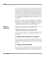
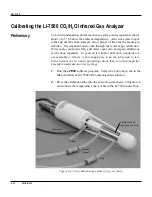
Insert the top of the fixture first, and slide the bottom into place. It
is very important that the fixture is centered between the windows
covering the source and detector modules. It can be helpful to
click on the Diagnostics tab in the 7500-50 software, and view the
AGC value while centering the fixture; if the AGC value increases
when the fixture is in place, it indicates that one or both of the
windows are partially or totally obscured. Move the fixture back
and forth until the AGC value reads the same value as before the
fixture was inserted. The fixture is very easy to center; if it looks
centered, it probably is.
NOTE: The three ports on the calibration tube are entirely
interchangeable.
3.
Click on the Calibration tab, and verify that temperature and
pressure sensors are working properly. (If you are using an
alternate source for temperature and pressure values, click on the
Inputs tab and set that up).
IMPORTANT NOTE: Always zero the instrument before
spanning (don’t span, then zero).
4.
Flow CO
2
-free air through the calibration fixture at a rate of about
0.5 to 1.0 LPM. Attach the zero gas to the calibration fixture at
one of the ports shown in Figure 4-4.


