LI-8100A
ACU
LI-8150
Pump
Subsample
Loop
Flow
Meter
Filter
Chamber
Solenoid Manifold
1 2 3 4 5 6 7 8
LI-8100A
ACU
LI-8150
Pump
Subsample
Loop
Flow
Meter
Flask
Auxiliary
Pump
Exhaust Line
8 7 6 5 4 3 2 1
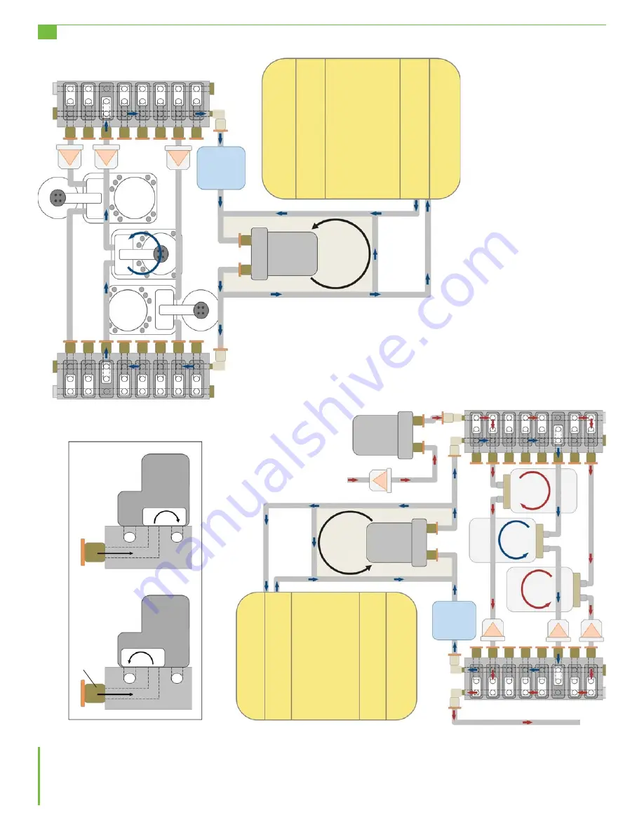
Figure 5.
Flow schematics for the LI-8150 configured for normal operation (top) and configured for flask measurements
(bottom right). The flow path used during measurements is shown with blue arrows and the flow path used to flush flasks
between measurements is shown with red arrows. In both diagrams the solenoids at port 3 are activated and the chamber
connected there is being sampled. The box in the lower left hand corner shows how the flow path changes inside the
solenoid manifold when a solenoid is activated.
A. Deactivated Solenoid
B. Activated Solenoid
Solenoid
Manifold
Quick
Connect
4


