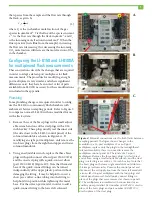
8. All ports that are not connected to a chamber, or
used to supply/vent air from the flasks should remain
capped with the black plastic caps supplied with the
LI-8150. If these have been misplaced, replacement
caps can be ordered from LI-COR using part #620-
08298 and 620-08299. One of each will be needed for
every unused port.
Powering the system
The 8150-770 AC Power Supply can be used to supply
power to the LI-8150 and LI-8100A, as well as the
auxiliary pump used for continuously flushing the flasks.
The 8150-770 is capable of providing up to 4.5 Amps at
12 VDC. When the auxiliary pump is installed as
described in this application note the input voltage to the
LI-8150 should not exceed a nominal 12VDC.
Software Setup
There are some software configuration changes that must
be made to use the LI-8150 and LI-8100A for multi-
plexed flask measurements. The bulk of these changes
are made under the Chamber tab of the Multiplexer
Configuration window and relate to defining the appro-
priate volumes and areas for the flux calculations.
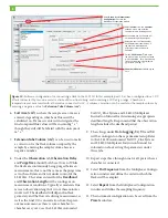
1. Under the
Setup
drop down menu in the main
LI-8100A Windows interface software window, select
Measurement Configuration
(Figure 10).
2. Select
Port Setup
from the Multiplexer Configura-
tion window.
3. In the
Chamber
tab, select
Custom
from the
Cham-
ber:
drop-down menu and enter the chamber
volume in cubic centimeters. Be sure to include the
volume of the tubing used to connect the flask to the
LI-8150 in the chamber volume
1
.
4. Make sure the closed signal check box is unchecked
and that the chamber offset is set to zero.
5. Select the chamber air temperature source from the
Temp Source dropdown menu. If the temperature
source is measured by a different port, skip this and
recompute with the correct temperature later. If
measurements are made at near ambient tempera-
tures a measurement of chamber air temperature
may not be required.
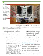
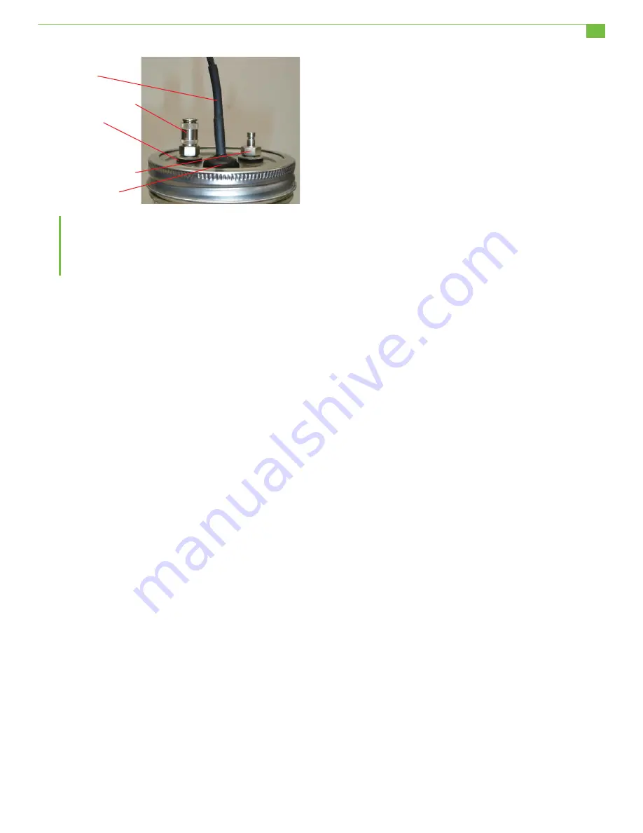
Figure 9.
Mason jar lid fitted with plumbing
connections and a soil temperature thermistor. Two 8
mm holes are drilled in the lid to install the quick
connect bulkheads and a 12 mm hole is drilled to
install the grommet for the thermistor.
either side of the lid, evenly spaced between the
larger hole and the edge of the lid (Figure 9).
2.
Place a seal washer (part #167-07256) on the
threaded portion of a female quick-connect bulk-
head fitting (part #300-07126) and install it in one of
the 8 mm holes using the nut and washer provided
with the fitting. Repeat this procedure for the other
8
mm hole using a male quick-connect bulkhead
fitting
(part #300-07127) (Figure 11).
3.
Insert a rubber grommet (part #196-10534) into the
12 mm hole.
4.
Gently push a soil temperature thermistor (part
#8150-203) through the hole in the grommet and
then pull back slightly to seal it. A small amount of
silicone grease (part #210-01958-1) can be used to
ease insertion of the thermistor. To get a good seal
the
grommet should fit tightly in the hole and against
the
thermistor.
5.
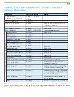
Two sections of Bev-a-line tubing are required to
connect each chamber to the LI-8150. Cut the
sections to the desired length and fit one end of each
tube with a female quick-connect (part #300-0712
5
)
and the other end with a male quick-connect (part
#300-0712
4
).
6.
Measure and record the length of each tube. This
information is very important and will be required
later when the chamber volume is entered for use in
the flux calculations.
7.
Attach the tubes to the fixtures on the lid of each
flask, and then to the selected port on the LI-8150.
1
To calculate the volume of Bev-a-line IV, multiply the length of
tubing used (in centimeters) by 0.0792. This will give volume in
cm
3
.
Soil temperature
thermistor
Female quick-connect
bulkhead (300-07126)
Male quick-connect
bulkhead (300-07127)
Rubber grommet
(196-10534)
Seal washer
7


