4617000L
Copyright © Liberty Pumps, Inc. 2019 All rights reserved.
5 | EN
Cords
LowPro systems come with two cords—one to the float switch and
the other to the pump motor. The float switch cord has a
piggyback (series) plug enabling the pump motor cord to be
plugged into the back of it. Both cords must be connected in
series for automatic operation.
The purpose of this design is to allow temporary manual
operation of the pump. For manual operation, or in the event of a
float switch failure, the pump cord can be separated and plugged
into the electrical outlet, directly bypassing the switch.
Use and Care
A routine of regular cleaning will keep the LowPro in good
working order. The exterior of the unit may be cleaned with a
damp cloth and normal household cleaners. Never spray or dump
water or chemicals directly on the unit.
Considerations
The LowPro41LP can be installed freestanding or built-in,
concealing the pump compartment and piping. The platform
section of the tank is sized to fit flush with an elevated floor
framed with 2" x 6" material.
Access to pump compartment
is required on built-in installations.
To accommodate future service, it is important to allow access to
the pump and switch cover when the unit is being framed-in with
a wall behind the water closet. This can be accomplished by
framing this portion of the tank into a closet, utility, or other
accessible room.
If installing walls or floor joists,
use caution to ensure that nails,
screws, or other sharp objects do not puncture the tank when
framing.
For addition of a sink or shower,
a rubber pipe seal is included
that accepts 2" schedule 40 PVC piping. Showers must be elevated
to allow gravity flow to unit.
If connecting a washing machine
, the preferred method is to
drain the washer into a tub sink with a lint sock prior to the
LowPro. This requires periodically removing the access cover to
clean lint and debris from the switch.
The tank installation location
must be level.
LowPro tank contains three
textured areas
acceptable
for installing rubber pipe
grommet.
Installation
outside of these areas
may result in damage to
internal components.
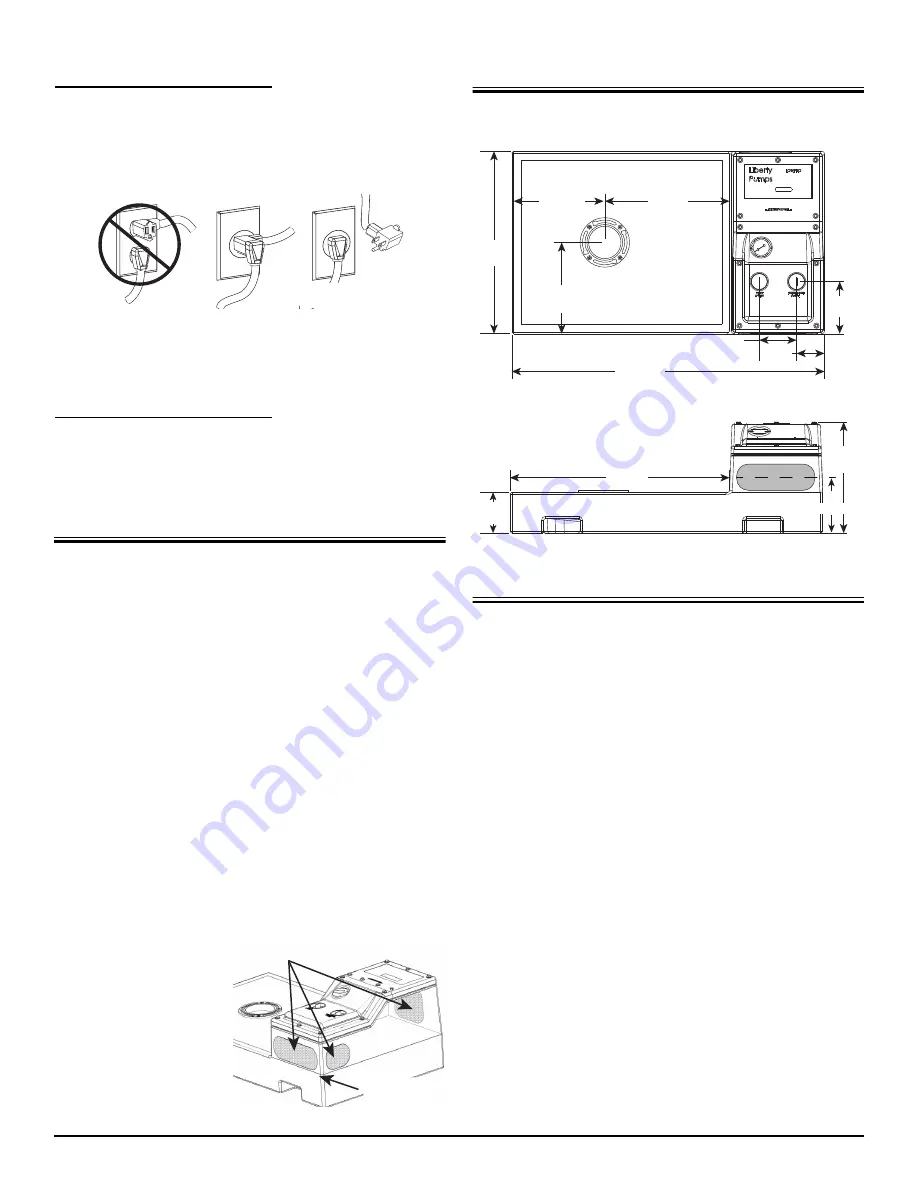
Dimensional Data
Installation
1.
Position the tank in its desired location and ensure that it is
level.
Use hydraulic cement or similar material for leveling the floor
if necessary.
2.
Determine the closest and most readily accessible locations
to tie in the discharge and vent lines to existing lines. Take the
necessary measurements and determine what plumbing
fittings and pipes are needed.
3.
An inlet for a 2" PVC drain line from additional fixtures (i.e.,
sink or shower) may be installed using the supplied rubber
pipe grommet.
Determine the best location for the drain line to enter the
tank—making sure it is within the marked textured areas of
the pump chamber.
Do not drill below or outside of the
textured areas.
Make sure drain lines have adequate gravity
flow to the system. If a shower is being used, elevate the
shower to allow for proper trapping and drainage.
4.
Drill a 3" diameter hole and insert the provided grommet.
Slide the 2" PVC drain line into the pipe grommet, lubricating
the pipe if necessary to ease installation.
5.
Install a 2" PVC pipe to the discharge connection on the
cover.
Threaded connections at tank require hand-tightening only.
Use thread seal tape to seal pipe threads.
Temporary Manual
Operation
YES!
NO!
Do Not Drill
Below This Line
Acceptable Rubber Pipe Grommet Locations
TOP VIEW
14-5/8”
[37 cm]
29-1/2”
[75 cm]
24-1/2”
[62 cm]
12-1/4”
[31 cm]
17”
[43 cm]
12-1/2”
[30.5 cm]
42”
[106.7 cm]
5”
[12.7 cm]
3-3/4”
[9.5 cm]
7”
[17.8 cm]
5-1/4”
[13.3 cm]
SIDE VIEW
7”
[17.8 cm]


