19
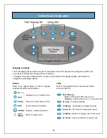
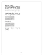
Buttons
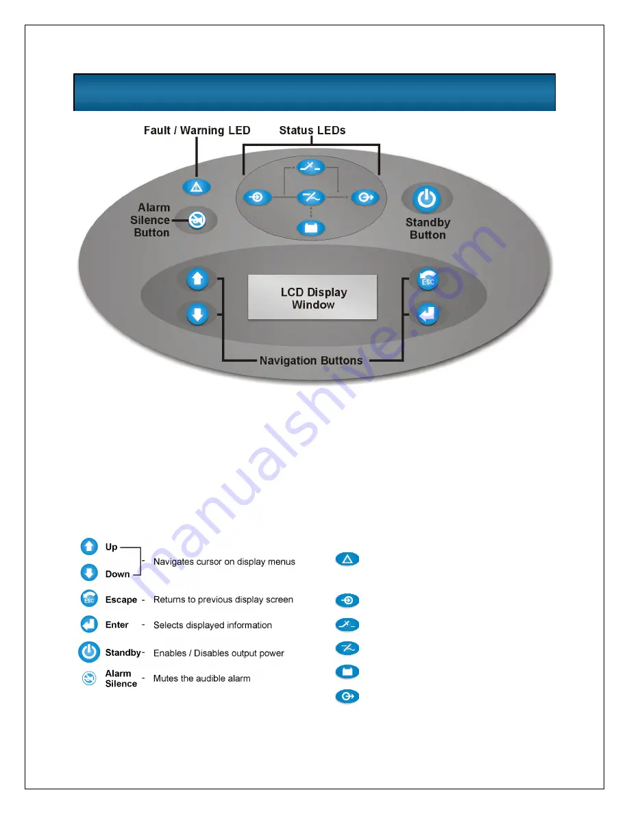
Refer to the legend below in order to properly
navigate the
Nfinity
User Interface.
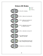
LEDs
Refer to the legend below to indicate occurrence
when an LED is lit.
Controls and Indicators
Display Controls
The Front Display Panel informs the user of the status of the UPS, and lets him configure the UPS to his
own needs or preferences through the user interface
.
It consists of a series of Status LED’s, a 4 line by 20 character LCD display window, and buttons for
navigation (as displayed above).
!
Fault / Warning
Solid-
Flashing-
A UPS fault condition has occured.
A Warning has occured. Consult event log.
AC Input
- AC utility is available
On Bypass
- The Bypass is supplying the power
Inverter On
- The Inverter is supplying the power
On Battery
- Battery is supplying power to the inverter
AC Output
- Power is available to supply the load
Summary of Contents for 12 bay
Page 1: ...User Manual English 208 V 240 V 60Hz 4 to 16 kVA Power System...
Page 2: ......
Page 4: ...2 Glossary of Symbols...
Page 5: ...3 Introduction General Description Modes of Operation Major Components...
Page 7: ...5...
Page 12: ...10 Installation Preparation Unloading Cable Installation Communications...
Page 20: ...18 Operating Instructions Controls and Indicators Operating Procedures Main Menu...
Page 33: ...31 Troubleshooting Alarm Messages Module LED Indication Module Replacement...
Page 38: ...36 Maintenance Proper Care Scheduled Maintenance Replacing Fan Filters...
Page 40: ...38 Reference Specifications Battery Run Times Warranty Technical Support...

