4
Congratulations on your purchase of Liebert’s
Nfinity™
Uninterruptible Power System. As with
every Liebert product, we stand behind our
quality. If you have any questions concerning
this UPS, please feel free to contact your local
sales representative, or call the appropriate
Technical Support number listed in the back of
this manual.
To ensure proper installation and operation of
this unit, please read this manual thoroughly.
SYSTEM DESCRIPTION
The Liebert
Nfinity
Power System is a modular
UPS intended for use with workstations, servers,
network, telecom or other sensitive electronic
equipment. It provides continuous, high-quality
AC power to your equipment, protecting it from
any power disturbance due to blackouts,
brownouts, surges or noise interference.
The
Nfinity
modular UPS was designed to
provide maximum system availability to business
critical equipment.
Nfinity
is also an easily
adaptable UPS system. By simply installing
additional power or battery modules you can
expand your current system capacity or extend
your back-up runtime.
Nfinity
has a comprehensive user interface that
can be configured according to the user’s
preference. It also informs the user of details on
the status of the UPS, and keeps a log of
events.
FEATURES:
§
Up to 16 kVA of modular back-up
power
§
Continuous power conditioning
§
A user-friendly interface for custom
configuration
§
Continuous system monitoring
§
Warning alarms and event logs
STANDARD COMPONENTS:
§
Power Modules – for power
conditioning
§
Battery Modules – for back-up power
§
System Control Modules – for system
monitoring and communications
§
LCD display for comprehensive user
indications and programmable controls
§
Output transformer for isolation
COMMUNICATIONS
§
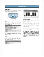
Dry contacts
§
RS-232
§
Optional communications via
Intellislot™ communication ports
General Description
Summary of Contents for 12 bay
Page 1: ...User Manual English 208 V 240 V 60Hz 4 to 16 kVA Power System...
Page 2: ......
Page 4: ...2 Glossary of Symbols...
Page 5: ...3 Introduction General Description Modes of Operation Major Components...
Page 7: ...5...
Page 12: ...10 Installation Preparation Unloading Cable Installation Communications...
Page 20: ...18 Operating Instructions Controls and Indicators Operating Procedures Main Menu...
Page 33: ...31 Troubleshooting Alarm Messages Module LED Indication Module Replacement...
Page 38: ...36 Maintenance Proper Care Scheduled Maintenance Replacing Fan Filters...
Page 40: ...38 Reference Specifications Battery Run Times Warranty Technical Support...


