
5
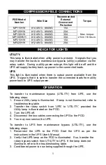
COMPRESSION FIELD CONNECTIONS
POD
Model
Number
Wire Size
Recommended
External
Overcurrent
Protection
Torque
MP115HW
#14 AWG - #8AWG
15A
MP120HW
#12 AWG - #8AWG
20A
MP130HW
#10 AWG - #8AWG
30A
MP130HWH
#10 AWG - #8AWG
30A
MP215HW
#14 AWG - #8AWG
15A
MP220HW
#12 AWG - #8AWG
20A
Max. torque:
2 Nm / 16 lbs-in.
INDICATOR LIGHTS
UTILITY:
This lamp is illuminated when utility power is present. It signals that you
may transfer the loads to maintenance bypass (utility) operation via the
rotary switch. During a utility power outage, this light will be off and the
UPS will supply battery back-up power to the connected loads.
UPS:
This light is illuminated when there is output power available from the
UPS. It signals that it is safe to transfer the connected loads from utility
power back to UPS output power.
OPERATION
To transfer to maintenance bypass (UTILITY) from UPS, use the
following steps:
1. Ensure Utility lamp is illuminated. If lamp is not illuminated, refer to
troubleshooting table.
2. Transfer the rotary switch from ‘UPS’ to ‘UTILITY’, provided the
Utility lamp is illuminated on the POD.
3. Turn the UPS off.
4. Disconnect the two cables connecting the UPS to the POD.
5. You may now service the UPS.
To transfer to UPS from maintenance bypass (UTILITY), use the
following steps:
1. Reconnect the UPS to the POD. Start the UPS as per the
instructions in the UPS User's Manual.
2. Verify that UPS lamp on the POD is illuminated. If so, transfer the
rotary bypass switch from UTILITY to UPS. If the lamp does not
illuminate, refer to the troubleshooting table.
3. Conditioned power is now being supplied through the UPS.