background image

Installing Optional Items

11

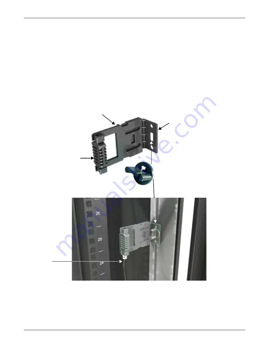
To install a sensor on a Knurr rack frame member:
1. Assemble the Liebert SN and sensor bracket:

a. Insert the sensor bracket base into one end of the sensor support as shown in 

Figure 11

.

b. Snap the sensor into the other end of the sensor support.

2. Choose where in the rack to install the sensor assembly. Emerson recommends placing the sensor 

in the area that is likely to be warmest.

3. Hold the sensor bracket on a T-slot on the Knurr rack frame where the sensor will be placed.
4. Insert the included quarter-turn fastener through the rectangular hole in the sensor bracket base 

and into the T-slot (see 

Figure 11

).

5. Turn the fastener clockwise 90 degrees, a quarter of a turn.
6. Route the sensor cable to the Liebert RPC and insert it into the card’s external sensor port.

For further details, refer to the Liebert RPC user manual, SL-20825, which shipped with the card 

and is available at Liebert’s Web site: 

www.liebert.com

Figure 11

Temperature/humidity sensor mounting

Sensor Bracket Base

Quarter-Turn Fastener
Rectangular protrusion passes 
through bracket slot (above) and 
into T-slot on Knurr rack frame 
member (below).

Sensor Support

Liebert SN Sensor
snapped into support

Liebert SN 
Sensor Cable

Summary of Contents for MPH-EBR09NXXO30

Page 1: ...AC Power For Business Critical Continuity Liebert MPH User Manual North American European Applications...

Page 2: ......

Page 3: ...4 2 2 RPC BDM Installation on Knurr Miracel Frame 9 4 3 Temperature Humidity Sensor Installation Optional 10 5 0 USING THE LIEBERT MPH 12 6 0 SPECIFICATIONS 13 6 1 Agency Approvals 15 6 2 Product War...

Page 4: ...ii...

Page 5: ...r burn Do not continue to use the Liebert MPH if the LED panel or monitoring interface indicators are not in accordance with these operating instructions Refer all faults to your local dealer Emerson...

Page 6: ...rt 15 of the FCC Rules Opera tion is subject to the following two conditions This device may not cause harmful interference and This device must accept any interference received including interference...

Page 7: ...city up to 22 1kW 230 400VAC 32A or 10 7kW 120 208VAC 30A For further details refer to 6 0 Specifications Remote monitoring is enabled by the included communication card the Liebert RPC which permits...

Page 8: ...Mount L6 20P or L6 30P plug connection 10 ft 3m input power cord 20 or 30A 27x IEC C13 or 21x IEC C13 plus 6x IEC C19 receptacles 68 25 in 1735mm long 200 240VAC Single Phase Input Output Rack Mount L...

Page 9: ...a frame member 1 Use four of the 6 32 screws to attach a bracket to each end of the Liebert MPH The supplied brackets have four holes that match holes on each end of the Liebert MPH If mounting on ho...

Page 10: ...o U Mount 6 Figure 3 Inserting a spring nut into a T slot Figure 4 Attaching a Liebert MPH to a Knurr rack horizontal frame member T slot Spring nut inserted into T slot leaf spring goes inside Tool l...

Page 11: ...of the unit The cord can be repositioned 90 if it will need to enter from the front To reposition the cord 1 Remove the four screws retaining the input power plate 2 Reposition 90 so that power cord e...

Page 12: ...dimensions of the Liebert MPH To attach the brackets 1 Hold one mounting bracket against the side of the Liebert MPH making sure that the end of the bracket with the round holes is against the unit 2...

Page 13: ...ble tie through the slot on the back of the module see Figure 9 Either method permits moving the RPC BDM to a different place in the same rack or to another rack 4 2 1 Mounting Hardware Spring nut M5...

Page 14: ...humidity levels Each connects to the Liebert RPC which makes readings available to Liebert monitoring methods Only one mounting method is addressed in this manual attaching a single sensor with a brac...

Page 15: ...sert the included quarter turn fastener through the rectangular hole in the sensor bracket base and into the T slot see Figure 11 5 Turn the fastener clockwise 90 degrees a quarter of a turn 6 Route t...

Page 16: ...3 Connect input power to the Liebert MPH 4 Route the rack equipment s power cables to the Liebert MPH following proper procedures and good practices such as segregating power cables from control cable...

Page 17: ...Vertical MPH EBV27NXXQ30 230 32 32 7 3 1 IEC 309 27 IEC C13 Vertical MPH EBV27NXXO30 230 16 16 3 6 1 IEC C20 27 IEC C13 Vertical MPH EBV27NOXR30 400 230 32 32 12 8 3 IEC 309 21 IEC C 13 6 IEC C 19 Ve...

Page 18: ...3 13 x 68 1 50 x 80 x 1730 17 25 x 7 0 x 1 73 438 x 178 x 44 mm Table 1 Liebert MPH Model numbers and specifications continued Part Number Input Output Form Factor Voltage Rated Amps Max Continuous A...

Page 19: ...ngs Directive 73 23 EEC CE Markings GS mark safety tested according to DIN EN 60950 1 VBE 0805 1 2006 95 EC and EMC Directive EMD 2004 108 EC according to the Low Voltage Directive LVD Electromagnetic...

Page 20: ...change without notice Liebert is a registered trademark of Liebert Corporation All names referred to are trademarks or registered trademarks of their respective owners Technical Support Service Web Si...

Reviews: