Chapter 7 Parallel System And LBS System 57
Liebert NXC 30kVA And 40kVA UPS User Manual
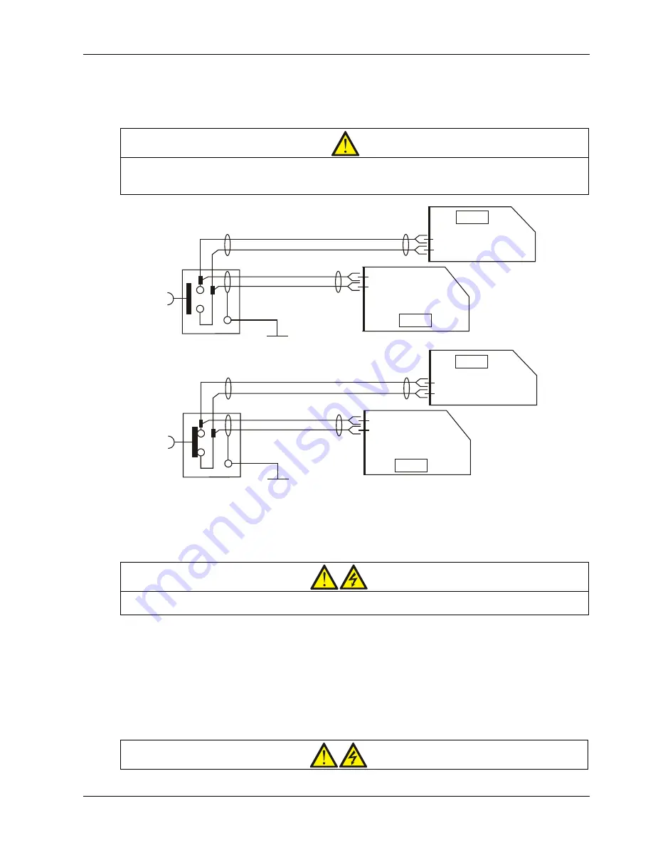
7.2.5 Remote EPO
In addition to the EPO switch provided on the operator control and display panel of each UPS module for controlling
the EPO of each module respectively, the parallel system also provides remote EPO function for controlling all UPS
modules to shut down simultaneously from a remote terminal, as shown in Figure 7-3.
Note
1. The remote EPO switch must provide dry contact signal, which is normally open or normally closed.
2. The open circuit voltage provided is 12Vdc, < 20mA.
3. The external EPO device can be composed of another control system which can disconnect UPS mains supply or bypass input.
Figure 7-3 EPO circuit diagram
Note: In Figure 7-3, the upper one is Normally Open type, and the lower one is Normally Closed type.
7.3 Operation Procedures For Parallel System
Warning
If UPS input uses RCD, differential switch is only used in the system’s bypass mains supply. At the moment of electrical
connection, current may not be immediately separated, which may result in the tripping of RCCB respectively.
Only one step is needed for once, and only after finishing this operation step of each UPS module, the next step can
be carried on.
7.3.1 Startup Procedures In Normal Mode
These procedures are applicable to start the UPS under total power-down state, which means the UPS or the
maintenance bypass switch has not supplied the load before. Make sure UPS has been completely installed and
commissioned by the engineer, and external power supply switch has been turned off.
Warning
J3 3.3
EPO
UPS1
EPO
UPS 2
UPS1
UPS 2
J3 3.4
J3 3.3
J3 3.4
J3 3.1
J3 3.2
J3 3.1
J3 3.2
board
Communication
Communication
board
Communication
board
Communication
board
Summary of Contents for NXC 30kVA
Page 2: ......


