Introduction to STS2/PDU Operations
70
8.1.2 Reliability and Agency Requirements
The STS2/PDU is designed for high reliability and high availability with a critical bus Mean Time
Between Failure (MTBF) exceeding 1,000,000 hours.
The STS2/PDU and all its options are designed, tested and certified, where applicable, to meet agency
requirements as follows:
• UL 891: Standard for Switchboard, for UL and ULc listing
• UL 1008: Standard for Automatic Transfer Switches
• UL 67: Standard for Panelboard
• UL 1561: Standard for Dry Transformers
• UL 1459: Telephone equipment (Modem)
• NEC
• FCC Part 15 EMI emission limits for Class A computing devices.
The STS2/PDU uses conservatively rated components, minimizing the need to go to maintenance
bypass. All normal maintenance and repair work can be done through the front panel of the unit. This
access makes repairs and maintenance easier.
Gating and control logic are partitioned so that failure of one source’s gating or sensing logic does not
prevent the switch from transferring to the other source.
All control and logic components are mounted separate from the power components. The STS2/PDU is
designed to minimize the exposure of hazardous voltages to allow safe servicing of the unit while the
load is energized.
All electrical components requiring normal maintenance are replaceable without de-energizing the
load, as long as one source is available. Solid-state switching devices are packaged to allow safe repair
of those devices without having to de-energize the load. All non-automatic switches or circuit breakers
are the plug-in or draw-out type to allow replacement without de-energizing the load. All other com-
ponents, including transformers, power cables and connections, circuit breaker bases, etc., are
replaceable from the front, rear or top of the unit—however, this requires all power to be removed
from the unit for safety. All solid-state power switching devices are rated to prevent hazardous device
failure in power systems with available fault currents up to the defined limits, as listed in
14.1.6 -
Electrical Requirements
.
8.1.3 Factory Backup and Service Assistance
Because improper installation can cause a system to fail, a Liebert Global Services or a factory
trained service technician should thoroughly inspect the unit to ensure it is properly installed and its
operating parameters are properly configured.
Once the STS2/PDU is properly installed, you, as the on-site operator, can easily monitor the unit’s
operation utilizing the touch screen.
In the United States, if you need assistance or have questions, call 1-800-LIEBERT (1-800-543-2378).
Outside the 48 contiguous United States, contact Liebert Global Services, if available in your area.
For international areas not covered by Liebert Global Services, the Liebert authorized distributor can
provide technical support.
8.2
Modes of Operation
8.2.1 Normal (Preferred Source)
Under normal operating conditions, the STS2/PDU routes power from the preferred input source to
the output load. The unit monitors the voltage current and phase of each source to ensure that both
are operating within set tolerances and that the alternate source is available, should a transfer be
required.
Summary of Contents for PDUTM
Page 25: ...Installation Drawings 17 7 0 INSTALLATION DRAWINGS Figure 7 Outline drawing 250A STS2 PDU ...
Page 42: ...Installation Drawings 34 Figure 24 Electrical field connections 250A STS2 PDU input with CB3 ...
Page 46: ...Installation Drawings 38 Figure 28 Electrical field connections 800A STS2 PDU input with CB3 ...
Page 63: ...Installation Drawings 55 Figure 45 Control wiring 800A STS2 PDU left side distribution ...
Page 64: ...Installation Drawings 56 Figure 46 Control wiring 800A STS2 PDU right side distribution ...
Page 65: ...Installation Drawings 57 Figure 47 Control connection location 250A STS2 PDU ...
Page 66: ...Installation Drawings 58 Figure 48 Control connection location 400 800A STS2 PDU ...
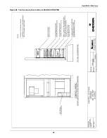
Page 68: ...Installation Drawings 60 Figure 50 Control wiring for the programmable relay board option ...
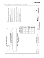
Page 69: ...Installation Drawings 61 Figure 51 Control wiring for the input contact isolator board option ...
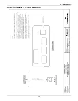
Page 70: ...Installation Drawings 62 Figure 52 Control wiring for comms board ...
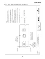
Page 71: ...Installation Drawings 63 Figure 53 Control wiring for the internal modem option ...
Page 72: ...Installation Drawings 64 Figure 54 Control wiring for the Network Interface Card NIC option ...
Page 73: ...Installation Drawings 65 Figure 55 Control wiring for the RS 232 Port ...
Page 74: ...Installation Drawings 66 Figure 56 Control wiring for remote source selection option ...
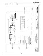
Page 75: ...Installation Drawings 67 Figure 57 Color LCD touch screen display ...
Page 155: ......


