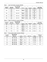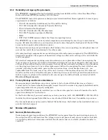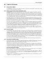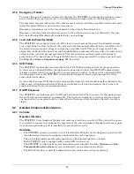
Operating Instructions
75
10.0 O
PERATING
I
NSTRUCTIONS
After the initial equipment start-up, the following operating guidelines can be used for standard equip-
ment operation. These guidelines should be reviewed for any special equipment modifications, special
site conditions or company policies that may require changes to the standard equipment operation.
All programmable functions are preset at the factory to enable the unit to be brought up without the
need to enter all selectable parameters.
The LCD touch screen is discussed in more detail in
13.0 - Touch Screen Display
.
See
Figures 23
through
36
for circuit breaker locations.
10.1 Normal System Turn-On
1. Depending on the type of distribution used:
• If equipped with output breaker CB8, open CB8.
• If equipped with output inline panelboards, open panelboard main breakers CB8 and CB9
and, if supplied, CB10 and CB11.
• If optional subfeed breakers are supplied, open subfeed breakers CB12 and CB13.
See
Figures 3
through
6
for location of breakers.
a. Retract the bolts on the key interlocks for CB1 and CB2.
b. Extend the bolts on the key interlocks for CB4 and CB5, thus preventing CB4 or CB5 from
being turned ON.
2. Apply source/input power to both STS2/PDU inputs by closing CB6 and CB7.
The touch screen control panel should become active and operate properly when at least one of the
inputs is energized.
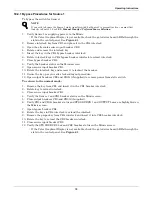
3. Verify that nominal input voltages are applied to both inputs (Source 1 and Source 2).
The input voltages, selected preferred source, breaker and switch status and alarms are indicated
on the Mimic screen.
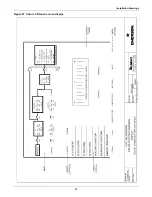
Figure 59 STS2/PDU touch screen display
!
CAUTION
Before unit is placed into service for the first time, after equipment relocation or after the
equipment has been de-energized for an extended period, a thorough equipment inspection
and supervised start-up by qualified personnel are strongly recommended. Contact your local
Liebert representative or Liebert Global Services at 1-800-543-2378 to arrange for equipment
inspection and start-up.
Mimic
Event display
Event controls
Sources
Static
Transfer
Switch
Summary of Contents for PDUTM
Page 25: ...Installation Drawings 17 7 0 INSTALLATION DRAWINGS Figure 7 Outline drawing 250A STS2 PDU ...
Page 42: ...Installation Drawings 34 Figure 24 Electrical field connections 250A STS2 PDU input with CB3 ...
Page 46: ...Installation Drawings 38 Figure 28 Electrical field connections 800A STS2 PDU input with CB3 ...
Page 63: ...Installation Drawings 55 Figure 45 Control wiring 800A STS2 PDU left side distribution ...
Page 64: ...Installation Drawings 56 Figure 46 Control wiring 800A STS2 PDU right side distribution ...
Page 65: ...Installation Drawings 57 Figure 47 Control connection location 250A STS2 PDU ...
Page 66: ...Installation Drawings 58 Figure 48 Control connection location 400 800A STS2 PDU ...
Page 68: ...Installation Drawings 60 Figure 50 Control wiring for the programmable relay board option ...
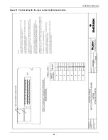
Page 69: ...Installation Drawings 61 Figure 51 Control wiring for the input contact isolator board option ...
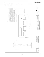
Page 70: ...Installation Drawings 62 Figure 52 Control wiring for comms board ...
Page 71: ...Installation Drawings 63 Figure 53 Control wiring for the internal modem option ...
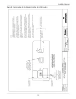
Page 72: ...Installation Drawings 64 Figure 54 Control wiring for the Network Interface Card NIC option ...
Page 73: ...Installation Drawings 65 Figure 55 Control wiring for the RS 232 Port ...
Page 74: ...Installation Drawings 66 Figure 56 Control wiring for remote source selection option ...
Page 75: ...Installation Drawings 67 Figure 57 Color LCD touch screen display ...
Page 155: ......

