Alarms and Faults
86
81
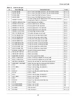
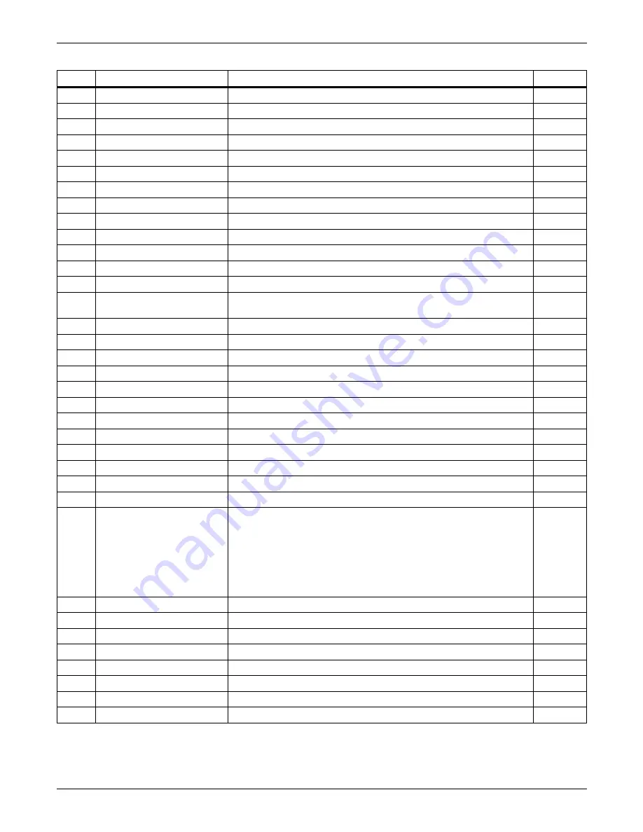
SOURCES OUT OF SYNC
Source 1 and Source 2 are out of synchronization.
A, E
82
LOAD ON ALT SOURCE
The output load is running on the alternate source.
A, E
83
AUTO REXFER INHIBIT
Automatic retransfer is inhibited.
A, E
84
CB1 (S1) OPEN
Source 1, Circuit Breaker 1 is open.
A, E
85
CB2 (S2) OPEN
Source 2, Circuit Breaker 2 is open.
A, E
86
CB4 (S1 BYP) CLOSED
Source 1 on bypass, Circuit Breaker 4 is closed.
A, E
87
CB5 (S2 BYP) CLOSED
Source 2 on bypass, Circuit Breaker 5 is closed.
A, E
88
CB3 (OUTPUT) OPEN
Output circuit breaker (CB3) is open.
A, E
89
CB3A (OUTPUT) OPEN
Output circuit breaker (CB3A) is open.
A, E
90
S1 PHASE ROT ERROR
Source 1 phase rotation error.
A, E
91
S2 PHASE ROT ERROR
Source 2 phase rotation error.
A, E
92
TRANSFER INHIBITED
Transfer inhibited.
A, E
93
OUTPUT UV
Output is under voltage.
D, F, A, E
94
HISTORY LOG FULL
Both History Logs have been written and no more history logs can be
written without clearing one of the logs
A, E
96
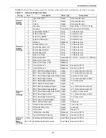
INPUT 1 OV INPUT
Source 1 over voltage
A, E
97
INPUT 1 UV INPUT
Source 1 under voltage
A, E
98
INPUT 2 OV INPUT
Source 2 over voltage
A, E
99
INPUT 2 UV INPUT
Source 2 under voltage
A, E
100
LOAD OVERCURRENT
Output over current
A, E
101
GROUND OVERCURRENT
Ground over current
A, E
102
NEUTRAL OVERCURRENT
Neutral over curremt
A, E
103
LOAD VOLTAGE THD
Voltage THD has exceeded the set limit
A, E
104
INPUT 1 CB6 OPEN
Source 1 input Circuit Breaker 6 is open
A, E
105
INPUT 2 CB7 OPEN
Source 2 Input Circuit Breaker 7 is open
A, E
106
INPUT 1 OF/UF
Source 1 over frequency/under frequency
A, E
107
INPUT 2 OF/UF
Source 2 over frequency/under frequency
A, E
120
121
122
123
124
125
126
127
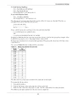
INPUT CONTACT #1
INPUT CONTACT #2
INPUT CONTACT #3
INPUT CONTACT #4
INPUT CONTACT #5
INPUT CONTACT #6
INPUT CONTACT #7
INPUT CONTACT #8
Input Contact #
x
is an optional alarm input. The alarm name can be
programmed with an alarm name from the Input Contactor Isolator
settings option under the Comm Options. See
Configuring the Input
Contact Isolator Settings on page 108
. The alarm is sent to Monitor
DSP. The LCD logs the alarm with the programmed name. Monitor
DSP logs it with the generic name which is how it is reported to the
SVT query.
A, E
128
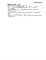
CONFIG MODIFIED
A setpoint configuration has changed.
E
129
PASSWORD CHANGED
The password for touch screen access has been modified and saved.
E
130
TIME REPROGRAMMED
The system’s time has been reset and saved.
E
131
DATE REPROGRAMMED
The system’s date has been reset and saved.
E
132
EVENT LOG CLEARED
The event log has been erased.
E
133
HIST LOGS CLEARED
Both History Logs have been erased.
E
134
XFER COUNT CLEARED
Transfer counter reset to 0
E
135
KWH COUNT CLEARED
KW-Hrs counter reset to 0
E
Table 12
Event messages (continued)
ID
Alarm Message
Description/Cause
Action
Summary of Contents for PDUTM
Page 25: ...Installation Drawings 17 7 0 INSTALLATION DRAWINGS Figure 7 Outline drawing 250A STS2 PDU ...
Page 42: ...Installation Drawings 34 Figure 24 Electrical field connections 250A STS2 PDU input with CB3 ...
Page 46: ...Installation Drawings 38 Figure 28 Electrical field connections 800A STS2 PDU input with CB3 ...
Page 63: ...Installation Drawings 55 Figure 45 Control wiring 800A STS2 PDU left side distribution ...
Page 64: ...Installation Drawings 56 Figure 46 Control wiring 800A STS2 PDU right side distribution ...
Page 65: ...Installation Drawings 57 Figure 47 Control connection location 250A STS2 PDU ...
Page 66: ...Installation Drawings 58 Figure 48 Control connection location 400 800A STS2 PDU ...
Page 68: ...Installation Drawings 60 Figure 50 Control wiring for the programmable relay board option ...
Page 69: ...Installation Drawings 61 Figure 51 Control wiring for the input contact isolator board option ...
Page 70: ...Installation Drawings 62 Figure 52 Control wiring for comms board ...
Page 71: ...Installation Drawings 63 Figure 53 Control wiring for the internal modem option ...
Page 72: ...Installation Drawings 64 Figure 54 Control wiring for the Network Interface Card NIC option ...
Page 73: ...Installation Drawings 65 Figure 55 Control wiring for the RS 232 Port ...
Page 74: ...Installation Drawings 66 Figure 56 Control wiring for remote source selection option ...
Page 75: ...Installation Drawings 67 Figure 57 Color LCD touch screen display ...
Page 155: ......

