background image

2

21

7

2

8

1

I

17

4

G

F

1

3

H

8. 

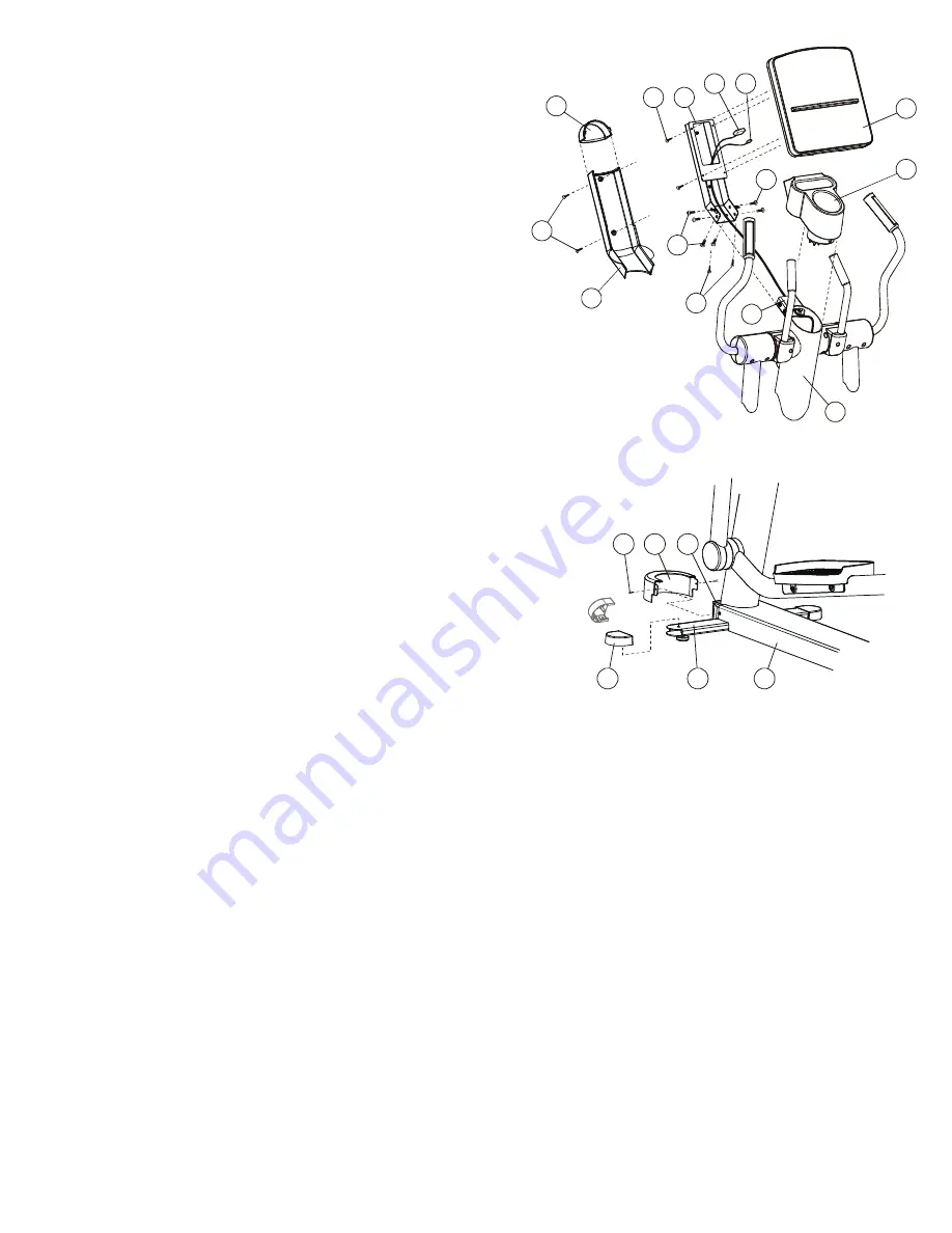
Locate the DISPLAY CONSOLE (4). Position the CONSOLE near the top 
of the CONSOLE BRACKET. Attach all CONNECTORS (F & G) leading 
from the CONSOLE BRACKET to their corresponding CONNECTORS in 
the back of the DISPLAY CONSOLE. Feed any excess WIRE HARNESS 
into the CONSOLE BRACKET and place the DISPLAY CONSOLE onto 
the CONSOLE BRACKET aligning the mounting holes. Secure the 
DISPLAY CONSOLE using four SCREWS (2). Tighten the SCREWS 
securely. Do not over-tighten the SCREWS. 

9. 

Locate the CONSOLE SUPPORT COVER (8). Position the CONSOLE 
BRACKET COVER over the underside of the CONSOLE SUPPORT 
ASSEMBLY (7) as shown and secure it using two SCREWS (2). Tighten 
the SCREWS securely. Do not over-tighten the SCREWS. 

10. 

Locate the CONSOLE SUPPORT CAP (21). Snap the CAP into position at 
the top of the CONSOLE SUPPORT COVER. 

11. 

Locate the BASE FRAME CAP (19). Remove the two SCREWS (J) 
securing the front of the BASE FRAME COVER (K) to the BASE FRAME 
(L). Position the CAP over the front of the BASE FRAME as shown sliding 
the mounting tabs to the inside of the BASE FRAME COVER. Secure the 
CAP using two SCREWS (J) previously removed. Tighten THE SCREWS 
securely. Do not over-tighten the SCREWS. 

12. 

Locate the four FOOT COVERS (20). Align the COVERS with the ends 
of the STABILIZER BARS (M). Insert the post on the underside of the 
FOOT COVERS into the mounting holes on the top of each STABILIZER. 
Press the FOOT COVERS firmly into position. 

13. 

Position the unit into the desired location for use. Properly level the unit 
according to the instructions in the Operation Manual. 


J

20

M

K

L

19

Summary of Contents for Classic Series Cross-Trainer CLSXH

Page 1: ...Classic Series Cross Trainer Model CLSXH Assembly Instructions...

Page 2: ...st and the step by step assembly procedures have been assembled to make the set up of the Cross Trainer as quick and easy as possible Please take special note of the following important points prior t...

Page 3: ...O ATTEMPTING TO OPERATE THIS MACHINE AS THIS IS ESSENTIAL FOR PROPER USE CONSIGNES DE SECURITE IMPORTANTES NE PLACEZ PAS L APPAREIL L EXT RIEUR PR S D UNE PISCINE OU DANS UN ENDROIT TR S HUMIDE NE FAI...

Page 4: ...upport Cover Qty 1 OK62 01023 0000 9 Front Pivot Arm Cover Qty 2 OK62 01012 0000 10 Rear Pivot Arm Cover Qty 2 OK62 01013 0000 11 Left User Arm Assembly Qty 1 AK62 00087 0000 12 Right User Arm Assembl...

Page 5: ...COVERS using two PHILLIPS PAN HEAD SCREWS 2 Tighten the SCREWS securely Do not over tighten the SCREWS 4 Locate the LEFT BULLHORN 13 Secure the BULLHORN to the BULLHORN MOUNTING BRACKET D using two F...

Page 6: ...ely Do not over tighten the SCREWS 10 Locate the CONSOLE SUPPORT CAP 21 Snap the CAP into position at the top of the CONSOLE SUPPORT COVER 11 Locate the BASE FRAME CAP 19 Remove the two SCREWS J secur...

Page 7: ...before using the Cross Trainer LISTE DES V RIFICATIONS EFFECTUER AVANT LA MISE EN MARCHE V rifiez si tous les dispositifs de fixation sont serr s V rifiez si l APPAREIL D EXERCICE POLYVALENT est de ni...

Page 8: ...eration Manual Life Fitness Customer Support Services 800 351 3737 or 847 451 0036 Prior to your call please be sure you have located and noted the MODEL NUMBER SERIAL NUMBER The Model Serial number i...

Reviews: