


PARTS LIST
PART #
72545
72550
72553
72555
72560
72564
72565
71126
68071
KEY
1
2
3
4
5
6
7
8
9
QTY
2
1
1
1
1
1
2
6
2
KEY
10
11
12
13
14
15
16
17
OR
PART #
3102922
3102905
3102906
3102807
3102514
6866701
6866601
6866602
6866603
DESCRIPTION
3/8 X 2-3/4” BOLT
3/8 X 3-3/4” BOLT
3/8 X 4” BOLT
3/8” LOW HEIGHT LOCK NUT
3/8” SAE WASHER
3/8” RH WASHER
BLACK RH CAP
WHITE RH CAP
PLATINUM RH CAP
QTY
4
26
4
32
58
66
18
48
48
DESCRIPTION
SIDE
TOP CROSS SUPPORT
RIGHT RAIL
LEFT RAIL
CHIN UP-SUPPORT
BOTTOM CROSS SUPPORT
REAR UPRIGHT
WEIGHT HORN
SMART RACK
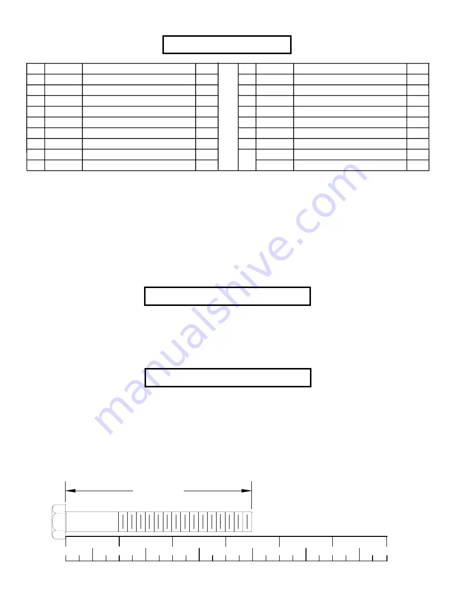
BOLT LENGTH
Tools Required for Assembly
2
NOTE: BOLT LENGTH IS MEASURED FROM THE UNDERSIDE OF THE HEAD OF THE BOLT.
Bolt Length Ruler
0
1
2
3
4
5
6
1/2
1/2
1/2
1/2
1/2
1/2
* Rubber mallet or hammer
* 9/16” wrench
* Ratchet with 9/16” socket
* 3mm Allen wrench


