background image

5

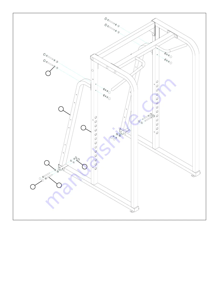
STEP 2:

FIGURE 2

11  3/8 X 3-3/4”

 7

 1

•  

 LOOSELY

 assemble the  two REAR UPRIGHTS (7) tot the SIDES (1) using sixteen RH CAPS (17), eight 3/8 X 3-3/4” BOLTS

(11), eight 3/8” SAE WASHERS (14), sixteen 3/8” RH WASHERS (15) and eight 3/8” LOW HEIGHT LOCK NUTS (13) as shown
in FIGURE 2.

17

15

13

14

Summary of Contents for Club Machine

Page 1: ...CLUB SERIES POWER RACK Part 72xxxx Rev A Revision 4 18 02 1 ASSEMBLY INSTRUCTIONS...

Page 2: ...EIGHT LOCK NUT 3 8 SAE WASHER 3 8 RH WASHER BLACK RH CAP WHITE RH CAP PLATINUM RH CAP QTY 4 26 4 32 58 66 18 48 48 DESCRIPTION SIDE TOP CROSS SUPPORT RIGHT RAIL LEFT RAIL CHIN UP SUPPORT BOTTOM CROSS...

Page 3: ...3 10 3 8 X 2 3 4 BOLT 12 3 8 X 4 BOLT 13 3 8 LOW HEIGHT LOCK NUT 14 3 8 SAE WASHER 17 RH CAP BLACK WHITE PLATINUM 15 RH WASHER 11 3 8 X 3 3 4 BOLT 16...

Page 4: ...SUPPORT 2 and the CHIN UP SUPPORT 5 using fourteen RH CAPS 17 eight 3 8 X 3 3 4 BOLTS 11 fourteen 3 8 SAE WASHERS 14 fourteen 3 8 RH WASHERS 15 and six 3 8 LOW HEIGHT LOCK NUTS 13 as shown in FIGURE 1...

Page 5: ...1 LOOSELY assemble the two REAR UPRIGHTS 7 tot the SIDES 1 using sixteen RH CAPS 17 eight 3 8 X 3 3 4 BOLTS 11 eight 3 8 SAE WASHERS 14 sixteen 3 8 RH WASHERS 15 and eight 3 8 LOW HEIGHT LOCK NUTS 13...

Page 6: ...he BOTTOM CROSS SUPPORT 6 to the REAR UPRIGHTS 7 and two WEIGHT HORNS 7 using four BLACK RH CAPS 16 four RH CAPS 17 four 3 8 X 4 BOLTS 12 eight 3 8 SAE WASHERS 14 eight 3 8 RH WASH ERS 15 and four 3 8...

Page 7: ...7 STEP 4 FIGURE 4 Securely tighten all loose frame connections made to this point then proceed to snap RH CAPS 16 17 over the RH WASHERS 25 on all tightened connections TIGHTEN TIGHTEN TIGHTEN TIGHTEN...

Page 8: ...mble the WEIGHT HORNS 7 to the REAR UPRIGHTS 7 using sixteen BLACK RH CAPS 16 sixteen RH CAPS 17 eight 3 8 X 3 3 4 BOLTS 11 sixteen 3 8 SAE WASHERS 14 sixteen 3 8 RH WASHERS 15 and eight 3 8 LOW HEIGH...

Page 9: ...the two SMART RACKS 9 to the SIDES 1 using six BLACK RH CAPS 16 six RH CAPS 17 six 3 8 X 3 3 4 BOLTS 11 twelve 3 8 SAE WASHERS 14 twelve 3 8 RH WASHERS 15 and six 3 8 LOW HEIGHT LOCK NUTS 13 as shown...

Page 10: ...10 STEP 7 FIGURE 7 CAREFULLY slide the RIGHT and LEFT RAIL 3 4 into the SIDES as shown in FIGURE 7 4 3 1 0 1 2 3 4 5 6 1 2 1 2 1 2 1 2 1 2 1 2...

Page 11: ...assumed by individuals who use this type of equipment To minimize risk please follow these rules 2 Do not allow minors or children to play on or around this equipment 1 Inspect equipment daily Tighte...

Reviews: