24
0
1
2
3
4
5
6
1/2
1/2
1/2
1/2
1/2
1/2
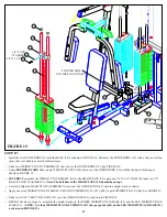
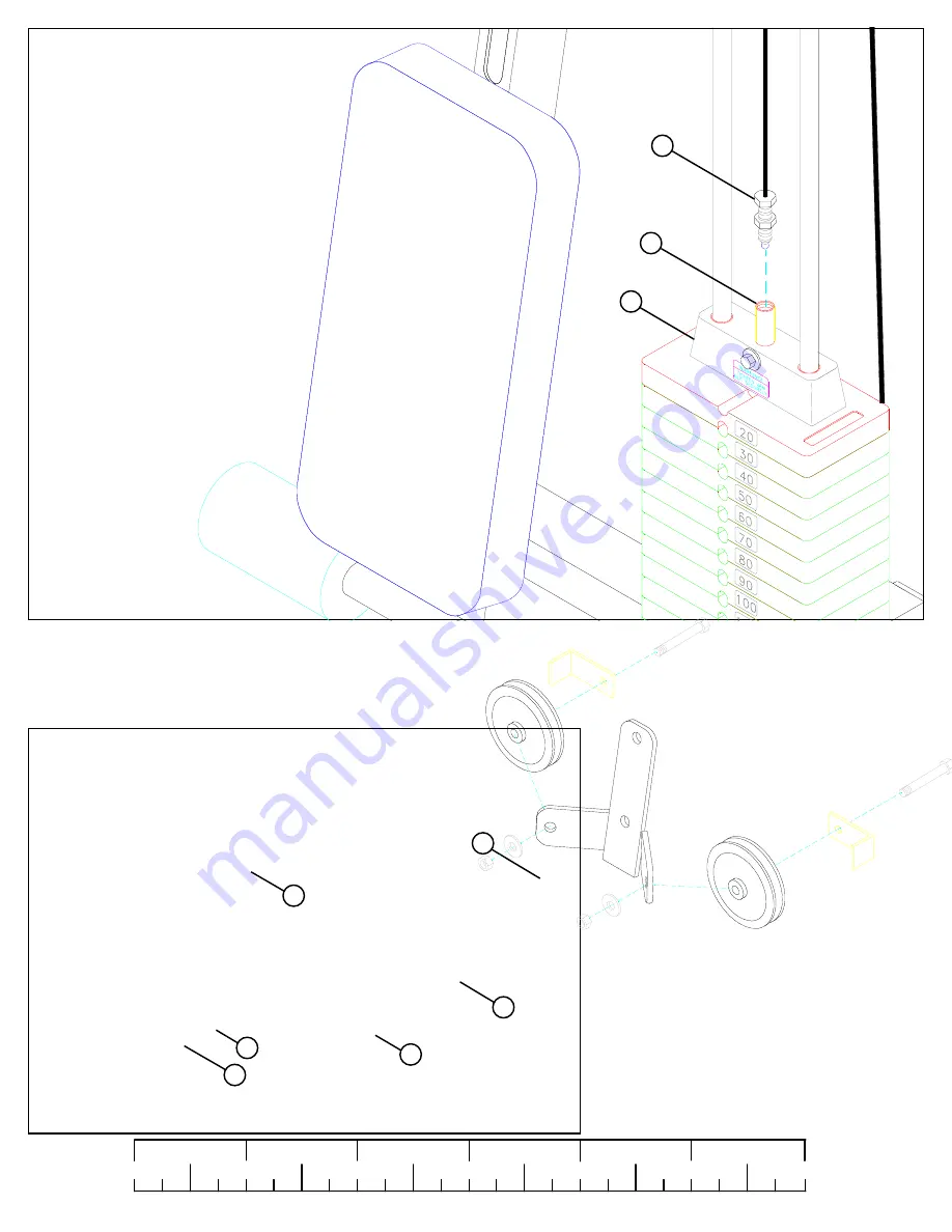
STEP 27:
FIGURE 27
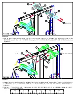
FIGURE 28
STEP 28:
•
LOOSELY
assemble two 4-1/2” PULLEYS (48)
to the CENTER PULLEY BRACKET (27) using
two 3/8 X 2” BOLTS (89), two 2-7/8” CABLE
CLIPS (67), two 3/8” WASHERS (80), and two
3/8” LOCK NUTS (82). See FIGURE 28.
•
Screw the threaded end of the LAT CABLE (42) approximately 1” into the end of the SELECTOR SHAFT (50) of the HEAD PLATE (53) as
shown in FIGURE 27.
3/8 X 2” 89
67
48
80
82
27
53
50
42
LAT
CABLE


