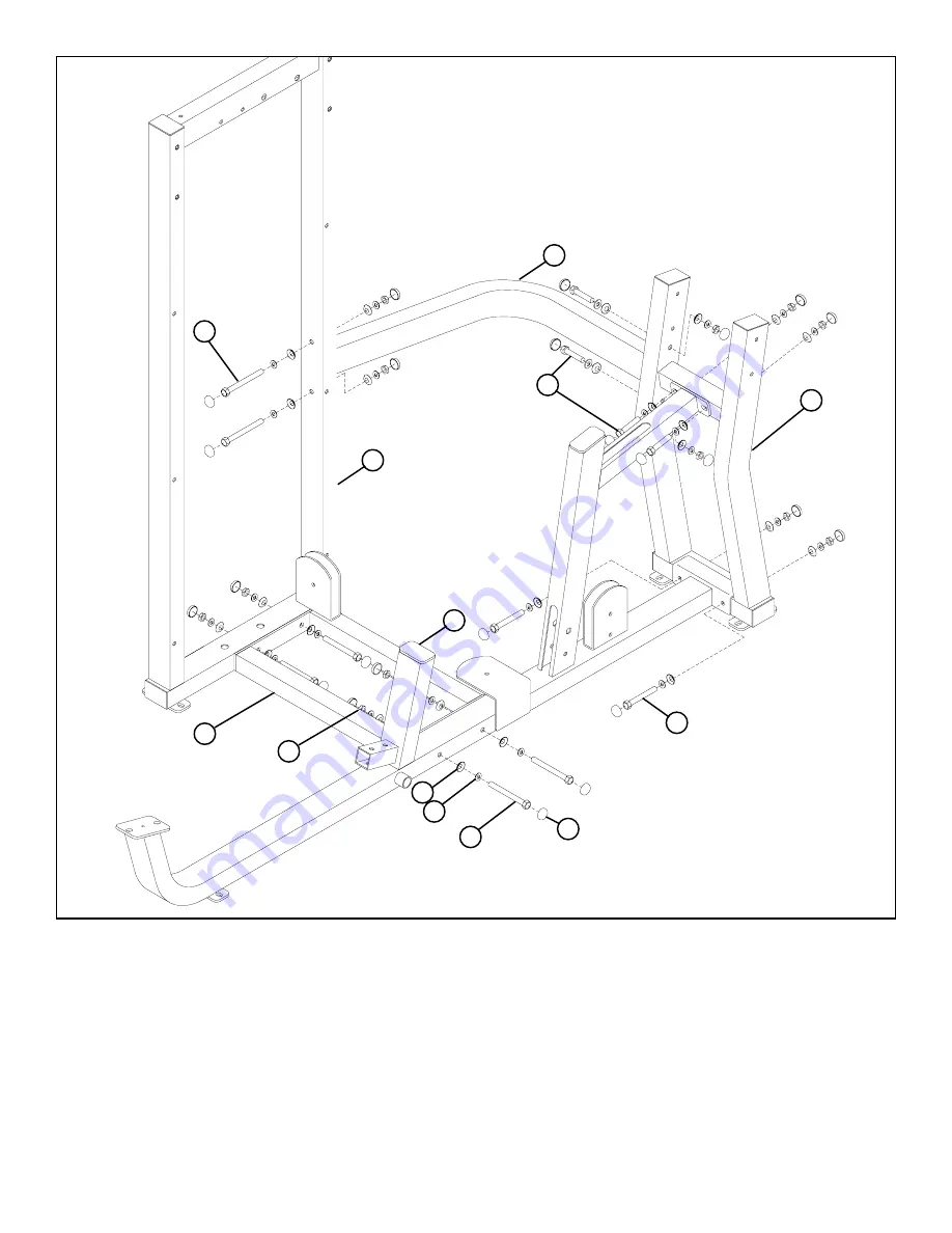
STEP 1:
FIGURE 1
5
•
LOOSELY
assemble the BASE (13) to the PRESS FRAME (8) and TOWER (1) using eight RH CAPS (53), four 3/8 X 90mm BOLTS
(42), eight 3/8” SAE WASHERS (50), eight 3/8” RH WASHERS (51) and four 3/8” LOW HEIGHT LOCK NUTS (49) as shown in FIG-
URE 1.
15
53
8
50
51
49
3/8 X 90mm 42
1
13
14
39 3/8 X 67mm
42 3/8 X 90mm
3/8 X 67mm 39
•
LOOSELY
assemble the REAR UPRIGHT (15) to the PRESS FRAME (8) and using eight RH CAPS (53), two 3/8 X 90mm BOLTS (42), two
3/8 X 67mm BOLTS (39), eight 3/8” SAE WASHERS (50), eight 3/8” RH WASHERS (51) and four 3/8” LOW HEIGHT LOCK NUTS (49)
as shown in FIGURE 1.
•
LOOSELY
assemble the UPPER SUPPORT (14) to the REAR UPRIGHT (15) and the TOWER (1) and using eight RH CAPS (53), four 3/
8 X 67mm BOLTS (39), eight 3/8” SAE WASHERS (50), eight 3/8” RH WASHERS (51) and four 3/8” LOW HEIGHT LOCK NUTS (49)
as shown in FIGURE 1.


