13
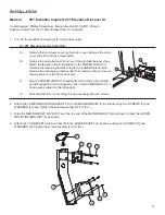
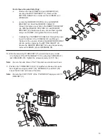
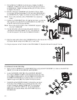
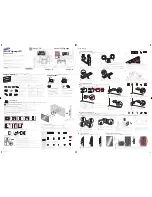
For Achieve Console Units Only:
a.
Remove the two SCREWS (A) and WASHERS (B)
securing the BOTTOM INSERT (C). Remove the
BOTTOM INSERT. Do not discard the SCREWS and
WASHERS.
b.
Locate the REMOTE CONTROL (D) and REMOTE
BRACKET (E). Feed the REMOTE CABLE (F)
through the large access hole in the REMOTE BRACKET
(E). With the REMOTE CONTROL (D) and REMOTE
BRACKET (E) oriented as shown, secure them together
using one SCREW. (G) Tighten the screw securely.
c.
Carefully feed the REMOTE CABLE (F) through the open-
ing in the bottom of the CONSOLE (H) and through
the back of the console. Position the REMOTE BRACKET
(E) into position replacing the BOTTOM INSERT (C).
Secure the REMOTE BRACKET (E) using the previously
removed SCREWS (A) and WASHERS (B).
10. With the remaining TV BRACKET (15) oriented as shown, install
it to the back of the ATTACHABLE TV (16) using four SCREWS (17)
and
WASHERS (18). Tighten the screws securely (8-10 ft. lbs.).
Note: Be sure the side holes of the TV bracket are oriented as shown.
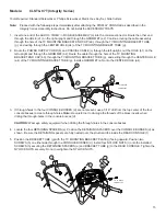
11.
Position the TV BRACKETS (8 & 15) together as shown and secure
them together using one BOLT (18), WASHER (19) and NUT (20).
Leave the bolt and nut loose at this time.
Note: Be sure the PIVOT POST of the TV BRACKET engages onto TV
BRACKET (8).
H
16
D
A
A
C
B
16
E
F
G
A
A
B
16
15
17
18
21
15
16
18
19
22
4
8
20
7
10


