background image

5.2

C

OACH

Z

ONE

D

ESCRIPTIONS

This section lists and describes the functions for the keys and LEDs on the CoachZone. 

A. WORKOUT ENHANCEMENT SELECTON 

KEYS:

Select the ArmToner or GluteToner to concentrate on specific upper body or lower body muscles. 

B. SELECTION INDICATOR LEDs:

A light next to the selected workout enhancement will illuminate. 

C. MUSCLE INDICATOR LEDs:

The Muscle Indicator LEDs show you which muscles should be utilized while performing specific movements. The 
bicep, chest, tricep, quad, calf, hamstring, and/or glutes will illuminate depending on your selection.

D. COACH INDICATOR LEDs:

The Coach Indicator LEDs prompt you to focus on one or more of the following movements: forward, squat, reverse,
push, use fixed handles, or pull.

E. UP/DOWN LEVEL KEYS:

Press the UP/DOWN Level Arrow Keys to increase or decrease either the resistance or difficulty level.

F.

TIMER

The amber LED timer displays a count down of time remaining for workout intervals 

(ranging from 15-60 seconds).

Note:

The CoachZone timer acts independently of the console timer.    

23

Summary of Contents for X3 Cross-Trainers

Page 1: ...x3 x3i CROSS TRAINER ASSEMBLY OPERATION MANUAL www lifefitness com Part 6985001 ...

Page 2: ... authorized service representative must perform any service other than cleaning or user maintenance There are no user serviceable parts This Operation Manual describes the functions of the Life Fitness X Series x3 x3i Cross Trainers Product specific features for each model are described in this manual under Specifications Life Fitness STRONGLY recommends consulting your doctor before undertaking a...

Page 3: ...1 10 Manual 19 5 1 11 EZ Resistance 19 5 1 12 Cool Down 19 5 1 13 Hill 20 5 1 14 Cross Train Aerobic 20 5 1 15 Cross Train Reverse 20 5 1 2 Zone Training 17 5 1 3 Fat Burn 17 5 1 4 Cardio 18 5 1 5 Heart Rate Hill And Heart Rate Interval Workouts 18 5 1 6 Heart Rate Interval 18 5 1 7 Sport Training 18 5 1 8 Extreme HR Workout 19 5 1 9 Random 19 5 2 Using The Workouts Chart 21 5 3 My Workouts 22 5 3...

Page 4: ...s near swimming pools or in areas of high humidity Never insert objects into any opening in this product If an object should drop inside turn off the power unplug the power cord from the outlet and carefully retrieve it If the item cannot be reached contact Life Fitness Customer Support Services Never place liquids of any type directly on the unit except in the optional accessory tray or holder Co...

Page 5: ...lt Qty 2 3 8 16 x 1 LONG 3223301 5 Upright Mounting Bolt Side Plate Qty 4 3 8 16 x 2 3 4 LONG 3223308 6 Front Clevis Pedal Lever Mounting Bolt Qty 2 3 8 16 x 3 1 4 LONG 3223310 7 Nylock Nut Low Height Qty 4 3 8 16 Low HT 3102807 8 Nylock Nut High Height Qty 2 3 8 16 3102802 9 Plastic Cap Retaining Washer Qty 10 6866701 10 Plastic Cap Black Qty 10 6866601 Not illustrated Plastic Clevis Covers Black...

Page 6: ...6 1 3 PARTS DESCRIPTION 1 0 2 3 5 3223308 3226003 3225905 3223401 3226603 3223301 The parts shown below are actual size and can be matched to the parts list on page 5 by the number next to them 4 ...

Page 7: ...7 1 3 PARTS DESCRIPTION CONTINUED 6 7 8 9 10 6866601 6866701 3223310 3102807 3102802 ...

Page 8: ...ic cables into wiring hole on upright tube assembly 3 Position upright tube assembly between plates on front of base frame Feed excess electronic cable into base frame NOTE This step could require two people 4 Line up holes on plates with holes on upright tube assembly 5 Connect upright tube assembly to base frame using four 5 2 3 4 bolts eight 9 washers 4 on each side and four 7 low profile nyloc...

Page 9: ...olts with a 9 16 socket wrench 8 Push the ten 10 black plastic cover caps over each bolt head STEP 3 Attach Plastic Upright Cap to upright assembly 1 Push the Plastic Upright Cap into open end of tube at the top of the upright assembly 2 Line up hole in nose cone with hole in upright assembly and fasten with a 3 screw 1 4 SETUP CONTINUED 3 10 Plastic Upright Cap Upright assembly ...

Page 10: ...cess cable s into opening of upright assembly NOTE 2 and 3 apply to model x3i only STEP 4 Attach heart rate accessory tray to upright assembly NOTE This step applies to model x3i only 1 Before attaching the accessory tray it is helpful to form the threads in the console plate Using a 3 8 socket wrench start the 0 self tapping screws into the holes When threads have formed remove the screws 2 Feed ...

Page 11: ...nch cables between the console and the console plate Be sure to get each screw started before fully tightening NOTE To avoid stripping do not over tighten screws STEP 7 Connect pedal levers to upper arms 1 Insert pedal lever into the clevis bracket of the upper arm 2 Connect pedal lever to upper arm using one 6 3 1 4 bolt and one 8 high profile nylock nut using a 9 16 socket wrench and a 9 16 open...

Page 12: ...brackets 1 Secure clevis cover to clevis bracket using two 1 10 tapping screws NOTE Threads are formed in the holes as the screw goes in A power screw driver is recommended if available 2 Repeat procedure for opposite side 1 4 SETUP CONTINUED ...

Page 13: ...n the floor Retighten the JAM NUT A B NOTE It is extremely important that the stabilizing leg be correctly adjusted for proper operation 1 6 PLUGGING IN THE CROSS TRAINER Your Life Fitness Cross Trainer comes with a standard U S power supply Insert the power adapter jack into the barrel plug on the back of the Cross Trainer Then insert the transformer into the wall outlet or the universal power su...

Page 14: ...anual Workout with the press of just one key F COOL DOWN KEY Begins an automatically customized cool down sequence G ZONE TRAINING HEART RATE CHART Quick reference chart used to identify your target heart rate H CT REVERSE Places the Monitor in CT Reverse mode I CLEAR PAUSE Pressing the PAUSE CLEAR button switches the monitor from any workout profile or mode to Pause mode Pressing the PAUSE CLEAR ...

Page 15: ...re pressing CLEAR PAUSE A WORKOUT PROFILE WINDOW A matrix of LED lights displays the current position and the upcoming terrain While striding the light columns move across the screen from right to left The higher the column of lights the greater the Level and workout intensity B MESSAGE CENTER Provides simple step by step instructions and motivational messages Displays Level Distance Speed Heart R...

Page 16: ...l between 60 and 75 of the theoretical maximum heart rate To improve cardiovascular condition work out at 75 to 85 of the theoretical maximum heart rate Life Fitness offers five exclusive workouts designed to take full advantage of the benefits of Heart Rate Zone Training The effect of the exercise activities can be varied by switching between the Fat Burn and Cardio workouts at any time during a ...

Page 17: ...ascular equipment The Fat Burn workout focuses on Heart Rate Zone Training at a level that maximizes the use of your body s fat stores for fuel Using an optional heart rate chest strap or the Lifepulse System it helps you maintain a specific heart rate 65 of a theoretical maximum heart rate within a target zone based on your age The result is a perfect workout every time eliminating both under and...

Page 18: ...at 1 minute once you reach your goal However if you don t reach the given goal you won t encounter any higher goals Your fitness level determines the number of hills and valleys you encounter Depending the time you set plus how fast and how high you climb your workout can end during any Target Heart Rate period 5 1 6 HEART RATE INTERVAL HEART RATE INTERVAL workout leads you through 2 intensity lev...

Page 19: ...evels below the workout level you would normally select for the Hill workout 5 1 10 MANUAL MANUAL is a steady pace workout that lets you change the resistance at any time during your workout The resistance levels here are equal to those of the highest hill encountered in the Hill workout at the same effort level Therefore it is recommended you start the Manual workout at about three to four levels...

Page 20: ...attern of the first four dropping back down to the level of the very first hill encountered This process repeats until the workout is complete 5 1 14 CROSS TRAIN AEROBIC X3i ONLY This workout makes the most of the Life Fitness Cross Trainer s total body workout capabilities by leading the user through a varied workout that exercises all the major muscle groups For an upper body workout that works ...

Page 21: ...ter weight Enter age Enter level Begin workout RANDOM Enter time Enter weight Enter age Enter level Begin workout EZ RESISTANCE Enter time Enter weight Enter age Enter level Begin workout EXTREME HR Enter time Enter weight Enter age Enter jog level Begin workout HEART RATE INTERVAL Enter time Enter weight Enter age Enter Target Heart Rate Begin workout CARDIO opt on x3 Enter time Enter weight Ente...

Page 22: ...n scrolls forward and pressing a button scrolls backwards through the alphanumeric characters 7 When the user has selected the character to be programmed pressing the Enter key accepts the letter and toggles the display to the next letter to be changed Repeat above 8 The user can press the Pause Clear button at any time while programming a name to erase the currently flashing letter 9 Pressing the...

Page 23: ...ode and return to Idle mode No workout information will be saved and the message center will display the previously saved workout or the default display the next time this mode is entered 5 3 6 STATISTICS DISPLAY 1 If the user presses the My Workout button when the message center is displaying PRESS ENTER TO EDIT WORKOUT PRESS MY WORKOUT TO ACCESS STATISTICS the monitor will show the statistics fo...

Page 24: ... mode Upon entering the User Menu the monitor will beep three times and enter User Menu programming state 1 Program State Setting Range Default Description 1 Pause Time 1 99 5 min Number of minutes a work out is paused 2 Sleep Time 1 99 off Off Number of minutes before sleepmode is entered Off is defined as no sleep mode 3 Hold Time 1 99 5 Number of seconds before the display toggles to the next p...

Page 25: ...nit down Do not move the unit or place hands into the unit while it is plugged into an electrical outlet 7 SERVICE AND TECHNICAL DATA Heart Rate Reading Is Erratic Or Absent Entirely Repeat the electrode wetting procedure see How to Use the Optional Heart Rate Monitor Chest Strap The electrodes must be wet to pick up and transmit accurate heart rate readings Make sure the electrodes are flat again...

Page 26: ...04 Sao Paulo BRAZIL Tel 055 11 7295 2217 Fax 055 11 7295 2218 LIFE FITNESS AUSTRIA Vertriebs Ges mbH Hintschiggasse 1 1100 Vienna AUSTRIA Tel 011 43 1 61 57 198 Fax 011 43 1 61 57 198 20 LIFE FITNESS BENELUX NV Lambrechtshoekenlaan 309 311 B 2170 Antwerpen Merksem BELGIUM Tel 011 32 3 644 44 88 Fax 011 32 3 644 24 80 LIFE FITNESS EUROPE GMBH Siemensstrasse 3 85716 Unterschleissheim GERMANY Tel 011...

Page 27: ...y Zone Console with Standard Not available Accessory Tray Heart Rate Control Standard Optional included accessory tray CT Reverse Standard Standard CT Aerobics Standard N A STRUCTURAL DESIGN Maximum User Weight 300 lbs 136 kg Frame 2 x 3 5 cm x 7 cm robotic welded steel frame Workout Profile LED display showing Not available workout progress Display Deluxe 16 character 10 character LED readout LED...

Page 28: ...www lifefitness com Part 6985001 ...

Page 29: ...X3 T O T A L B O D Y E L L I P T I C A L C R O S S T R A I N E R B A S E U S E R M A N U A L ...

Page 30: ...8 Alphaville Barueri SP 06465 140 BRAZIL LIFE FITNESS VERTRIEBS GMBH Dückegasse 7 9 3 36 1220 Vienna AUSTRIA LIFE FITNESS IBERIA C Frederic Mompou 5 1º 1º 08960 Sant Just Desvern Barcelona SPAIN LIFE FITNESS EUROPE GMBH Siemensstrasse 3 85716 Unterschleissheim GERMANY LIFE FITNESS ITALIA S R L Via Crivellin 7 N 37010 AFFI Verona ITALY LIFE FITNESS LATIN AMERICA and CARIBBEAN 5100 North River Road ...

Page 31: ... are designed to provide reasonable protection against harmful interference in a resi dential installation This equipment generates uses and can radiate radio frequency energy and if not installed and used in accordance with the user manual may cause harmful interference to radio communications However there is no guarantee that the interference will not occur in a particular installation If this ...

Page 32: ...iptical pedaling where resistance is independent of speed with push pull arm motion to provide an efficient effective total body workout Health related injuries may result from incorrect or excessive use of exercise equipment The manufacturer STRONGLY recommends seeing a physician for a complete medical exam before undertaking an exercise pro gram particularly if the user has a family history of h...

Page 33: ...ical Cross Trainer How To Stabilize The Total Body Elliptical Cross Trainer Powering Up The Total Body Elliptical Cross Trainer Mounting The Machine 4 Main Features 19 Contact Heart Rate Accessories Cushioned Pedal Insert 5 CoachZone 21 5 1 CoachZone Overview 21 5 2 CoachZone Descriptions 23 5 3 ArmToner 24 5 4 GluteToner 26 5 5 Timer 28 5 6 Resistance Level And Intensity Level 28 5 7 CoachZone Se...

Page 34: ... Pay Special Attention To Parts That Are Subject To Wear Outlined In The Preventative Maintenance Schedule 6 3 How To Obtain Product Service 33 7 Specifications 34 8 Warranty Information 35 What Is Covered Who Is Covered How Long Is It Covered Who Pays Shipping And Insurance For Service What We Will Do To Correct Covered Defects What Is Not Covered What You Must Do User Manual Product Registration...

Page 35: ...stomer Support Services Never place liquids of any type directly on the unit except in an accessory tray Containers with lids are recommended Do not use the Total Body Elliptical Cross Trainer outdoors near swimming pools or in areas of high humidity Keep all loose clothing shoelaces and towels away from the Total Body Elliptical Cross Trainer pedals Keep the area around the Total Body Elliptical ...

Page 36: ...all components are fastened securely The heart rate hand pulse sensors provide an approximate heart rate value The sensors are not medical devices and should not be used in any type of medical application SAVE THESE INSTRUCTIONS FOR FUTURE REFERENCE DANGER To reduce the risk of electrical shock Always unplug this appliance from the electrical outlet immediately after using and before cleaning SAFE...

Page 37: ...nto water Return the appliance to a service center for examination and repair Do not carry this appliance by supply cord or use cord as a handle Keep the cord away from heated surfaces Never operate the appliance with the air openings blocked Keep the air openings free of lint hair and the like Never drop or insert any object into any opening Do not use outdoors Do not operate where aerosol spray ...

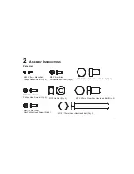
Page 38: ...crew Qty 6 M5 X 12mm Black Phillips Head Screw Qty 4 M5 X 12mm Clear Zinc Phillips Head Screw Qty 8 M5 X 8mm Black Phillips Head Screw Qty 4 M10 Hex Nut Qty 2 M10 X 15mm Silver Hex Head Bolt Qty 4 M10 X 20mm Clear Zinc Hex Head Bolt Qty 3 M10 X 70mm Silver Hex Head Bolt Qty 3 ...

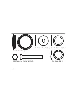
Page 39: ...10 Flat Washer 10mm ID Qty 2 Large Flat Washer Qty 2 M10 X 74mm Black Hex Head Bolt Qty 2 Wave Washer Qty 2 Plastic End Cap Qty 2 ...

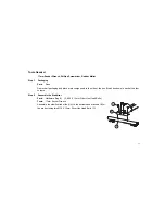
Page 40: ...main components to the side of the box Break box down in each of the four corners Step 2 Assemble the Stabilizer Parts Hardware Bag 1 2 M10 X 15mm Silver Hex Head Bolts Tools 17mm Socket Wrench Assemble the stabilizer tube foot A to the bottom base brackets B of the product using two M10 X 15mm Silver Hex Head Bolts C 11 C A B ...

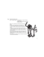
Page 41: ...o that you can simply lift the upright into place by pivoting upward Hold the upright in place and install three M10 X 70mm Silver Hex Head Bolts E into the side of the main bracket F Install one M10 X 20mm Clear Zinc Hex Head Bolt G into the front of the bracket CAUTION Do not pinch wires when assembling the upright Step 4 Connect Base Wiring Parts None Connect the two plugs H at the base of the ...

Page 42: ...gainst the pre installed stop ring L Locate the user right rocker arm assembly M marked with an R With the top handgrip facing the front of the unit slide the right rocker arm assembly onto the user right pivot shaft until seated against the washers Secure the rocker arm assembly to the pivot shaft using one Flat Washer N and one M10 X 20mm Clear Zinc Hex Head Bolt O Tighten the bolt securely Repe...

Page 43: ...rm clevis R Secure the pedal lever to the rocker arm clevis using one M10 X 74mm Hex Head Bolt S and one M10 Hex Nut T Tighten the bolt and nut securely Repeat the proce dure for the right pedal lever and rocker arm clevis Attach the left side lower pivot covers U over the moving arm pedal arm pivot point Snap the cover together over the moving arm pedal arm pivot point and use two M5 X 8mm Black ...

Page 44: ...rewdriver 17mm Socket Wrench Position the left side base shroud W over the metal bracket X and screw in with four M5 X 12mm Black Phillips Head Screws Y Repeat for the right side base shroud Slide the console bracket Z into the upright Use two M10 X 15mm Silver Hex Head Bolts A1 to attach the console bracket to the upright Note Avoid pinching the console wires 15 Z A1 W Y Y X ...

Page 45: ... place 3 Plug in the flat 6 pin 6P connector for the CoachZone 4 Push excess cable s into the opening of the upright tube assembly 5 Plug the spade connector attached to the console plate into the connector GR lead ing from the back of the display console Line up the four holes in the console bracket with the four holes in the back of the display console Attach the display console using four M5 X ...

Page 46: ...the Total Body Elliptical Cross Trainer from the side CAUTION Make certain you have plenty of room for the swing of the moving arms CAUTION Place the Total Body Elliptical Cross Trainer in a dry place Do not place in highly humid areas like near swimming pools as rust and corrosion may occur HOW TO STABILIZE THE TOTAL BODY ELLIPTICAL CROSS TRAINER Once the cross trainer is positioned in the room l...

Page 47: ... main LCD display lights up and press a button on the CoachZone to make sure it is powered If not recheck the plug and the wall connections and make sure the wall outlet has power MOUNTING THE MACHINE When mounting the machine it is recommended that the pedal closest to you is in its lowest position This can be done by pushing the arms to rotate the pedal until it is centered to the side of you at...

Page 48: ...he most accurate reading use a comfortable grip The console will show a heart rate reading after 15 to 20 seconds Hand pulse sensors can work differently with different body types With some individuals it can be very difficult to extract a heart rate reading Follow the tips below to improve the heart rate reading Remove your hands from the heart rate sensors and wait for the heart rate display to ...

Page 49: ...RIES The X3 comes standard with two water bottle holders C and an accessory tray D CUSHIONED PEDAL INSERT The X3 comes equipped with a cushioned pedal insert E for increased comfort during workouts 20 C C D E ...

Page 50: ...he workout into manageable increments The appropriate muscle groups that you should be using will illuminate when you perform specific movements The UP DOWN level arrow keys are a convenient way for users to change difficulty levels USING THE COACHZONE Select a workout from the main console display Begin workout At any point during a workout choose a CoachZone workout enhancement ArmToner or Glute...

Page 51: ...22 A A F C E E D D B B ...

Page 52: ...e utilized while performing specific movements The bicep chest tricep quad calf hamstring and or glutes will illuminate depending on your selection D COACH INDICATOR LEDs The Coach Indicator LEDs prompt you to focus on one or more of the following movements forward squat reverse push use fixed handles or pull E UP DOWN LEVEL KEYS Press the UP DOWN Level Arrow Keys to increase or decrease either th...

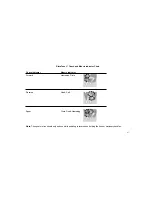
Page 53: ...lly shuts off if the ArmToner key isn t pressed within 5 minutes STOP ARMTONER Press and hold the ArmToner key while using the ArmToner selection The timer and coaching will cease The CoachZone automatically shuts down after 5 minutes of non use DISPLAY CHANGES The following blue coach indicator LEDs will activate and prompt you to focus on certain upper body movements push pull and use fixed hand...

Page 54: ... and Muscle Indicator Chart Coach Indicator Muscle Indicator Push Chest Tricep Pull Bicep Use Fixed Handles Upper body gets a rest Note Upper body motions will always work in conjunction with lower body movements 25 ...

Page 55: ... GluteToner key again to resume STOP GLUTETONER Press and hold the GluteToner key while using the GluteToner selection The timer and coaching will cease The CoachZone automatically shuts down after 5 minutes of non use DISPLAY CHANGES The following amber coach indicator LEDs will activate and prompt you to focus on certain lower body movements forward reverse and squat The corresponding amber musc...

Page 56: ...ndicator Chart Coach Indicator Muscle Indicator Forward Hamstring Glute Reverse Quad Calf Squat Glute Quad Hamstring Note The squat motion should only be done while pedaling in reverse and holding the fixed or stationary handles 27 ...

Page 57: ...y function after a user selects and begins a workout using the X3 main console The UP DOWN Level Arrow Keys control the brake resistance level 1 20 during a Quick Start or Manual workout The UP DOWN Level Arrow Keys control the overall difficulty level 1 20 with corresponding ranges during the following workouts Random Hill EZ Incline and Sports Training MAIN CONSOLE DISPLAY CHANGES The digital re...

Page 58: ...n the CoachZone is idle They cannot be changed while using a workout enhancement ATTRACT DISPLAY The user can choose to have an attract screen shown in place of the default dark sleep display It will repeatedly show a sequence of lights and a countdown from 5 to 0 The attract screen setting can be enabled or disabled by pressing and holding the GluteToner and ArmToner keys simultaneously for five ...

Page 59: ...ery difficult to extract a heart rate reading Follow the tips below to improve the heart rate reading Remove your hands from the heart rate sensors and wait for the heart rate display to clear Grasp sensors again Make sure hands are fully contacting the sensors Dry hands periodically during use Limit movement Clean hand pulse sensors May need to wait longer for heart rate to display Note The heart...

Page 60: ... Some noise from the pedals is normal It will vary depending on the weight of the user Check accessible hardware beneath pedal to make certain it is tight NOISE WITH INCREASED SPEED It is normal for any mechanical device to become louder as speed increases START UP RESISTANCE SEEMS VERY DIFFICULT Turn the unit off and then on again CAN T FEEL A RESISTANCE CHANGE AT THE BEGINNING LEVELS The resista...

Page 61: ...enance tips will keep the Total Body Elliptical Cross Trainer operating at peak perform ance Locate the Total Body Elliptical Cross Trainer in a cool dry place Clean the top surface of the pedals when needed Use a 100 cotton cloth lightly moistened with water or a mild liquid cleaning product to clean the product Other fabrics including paper towels may scratch the surface of the product Do not us...

Page 62: ...ice Internationally Life Fitness Europe GmbH Telephone 49 089 317 751 66 FAX 49 089 317 751 38 Life Fitness UK LTD Telephone 44 1353 665507 FAX 44 1353 666018 Life Fitness Atlantic BV Life Fitness Benelux Telephone 31 0 180 64 66 66 FAX 31 0 180 64 66 99 Life Fitness Italia S R L Telephone 39 0457 237 811 FAX 39 0457 238 197 Toll free telephone 800 438836 Life Fitness Vertriebs GmbH Telephone 43 1...

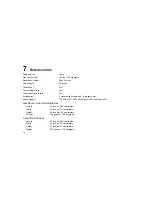
Page 63: ... water bottle holders and 1 accessory tray Power Supply 120 Volt U S 220 Volt Europe 240 Volt Australia ASSEMBLED WORKING DIMENSIONS Length 81 inches 206 centimeters Width 30 inches 76 centimeters Height 59 inches 150 centimeters Weight 225 pounds 102 kilograms SHIPPING DIMENSIONS Length 81 inches 206 centimeters Width 21 inches 53 centimeters Height 32 inches 81 centimeters Weight 242 pounds 110 ...

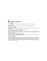
Page 64: ...shipping and insurance charges after the warranty has expired WHAT WE WILL DO TO CORRECT COVERED DEFECTS We will ship to you any new or rebuilt replacement part or component or at our option replace the Product Such replacement parts are warranted for the remaining portion of the original warranty period WHAT IS NOT COVERED Any failures or damage caused by unauthorized service misuse accident negl...

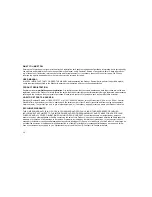
Page 65: ...T PARTS SERVICE Simply call Customer Service at 1 800 351 3737 or 1 847 288 3300 Monday through Friday from 8 00 a m to 5 00 p m Central Standard Time and tell them your name address and the serial number of your Product consoles and frames may have separate serial numbers They will tell you how to get a replacement part or if necessary arrange for service where your Product is located EXCLUSIVE W...

Page 66: ...ves you specific legal rights and you may have other rights which vary from state to state WARRANTY PERIODS MODEL LIFETIME 7 YEARS 5 YEARS 3 YEARS 1 YEAR MODEL LIFETIME 3 YEARS 2 YEARS 1 YEAR 6 MONTHS X3 Frame Electrical Parts Console Labor Cushioned Mechanical Parts All LCD displays Pedal Base Unit circuit boards Insert Note Warranties outside the U S may vary ...

Page 67: ...emier fitness equipment for the home T O T A L B O D Y E L L I P T I C A L C R O S S T R A I N E R S T R E A D M I L L S L I F E C Y C L E E X E R C I S E B I K E S G Y M S Y S T E M S 2006 Life Fitness a division of Brunswick Corporation All rights reserved Life Fitness is a registered trademark of Brunswick Corporation 8592001 Rev C 3 09 08 ...

Reviews: