9
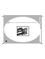
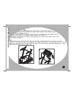
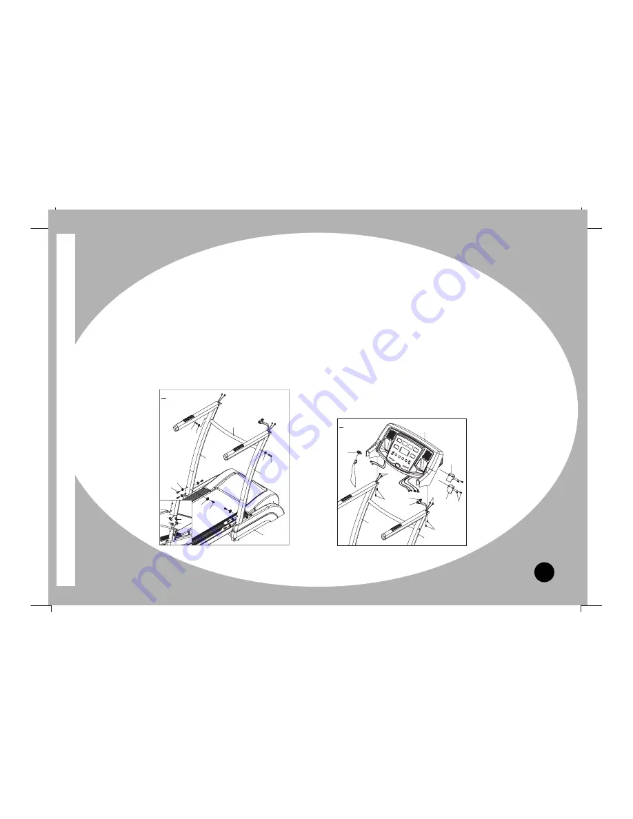
Step 2
Connect the Bottom Section Power Wire (25) and Sensor Cable I (78) from the
Stabilizer (34) to the Middle Section Power Wire (26) and Sensor Cable II (79) from the Right
Handlebar Support (35R).
Attach the Right and Left Handlebar Supports (35R, 35L) onto the Stabilizer (34) with eight M8x15mm. Bolts
(56), six Ø 8.4xØ 16xt1.6 Curve Washers (76), and two Ø 8.4xØ 16xt1.6 Washers (75).
Attach the Center Bar (39) onto the Right and Left Handlebar Supports (35R, 35L) with two M8x50mm. Bolts (51) and
Ø 8.4xØ 16xt1.6 Washers (75).
Step 3
Connect the Middle Section Power Wire (26), Hand Pulse Sensor Wires (32), and Sensor Cable II (79) to the wires that come from the
Computer (22). Then attach the Computer (22) to the Right and Left Handlebar Supports (35R, 35L) with four M6x15mm. Bolts (57). Attach the
Right and Left Computer Plates (24R, 24L) onto the back of the Computer (22) with four M4x22mm. Round Head Phillips Screws (67). Finally,
install the Safety Tether Key (27) onto the Computer (22).
ASSEMBL
Y
INSTRUCTIONS
56
56
76
75
34
35R
35L
39
51
75
75
51
79
78
25
26
79
35R
35L
22
24R
24L
27
32
57
67
57
32
26
3
2


