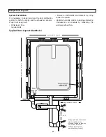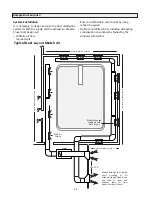
19
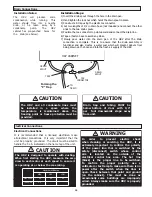
Installation Notes:
The
HRV
will
produce
some
condensation while running. This
water should flow into a nearby
drain, or be taken away by a
condensate
pump.
The
HRV
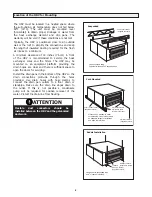
cabinet has pre-punched holes for
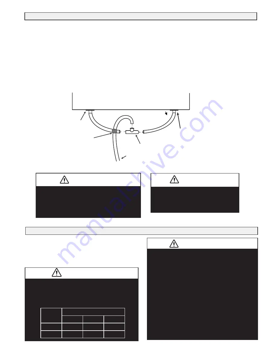
the drain (see below).
Drain
Connections
Electrical
Connections
Electrical
Connections
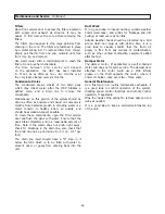
It is recommended that a licensed electrician make
all electrical connections. It is very important that the
unit be properly grounded.
The circuit must be sized to
handle the F.L.A. indicated on the name tag of the unit.
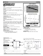
DRAIN
SPOUT
TAPE
TO
DRAIN
TEE
CONNECTOR
DRAIN
SPOUT
HRV CABINET
The
HRV
and
all
condensate
lines
must
be
installed
in
a
space
where
the
temperature
is
maintained
above the
freezing point or freeze
protection
must
be
provided.
Drain
trap
and
tubing
MUST
be
below
bottom
of
door
with
1/4"
per
foot
downwards
slope
away
from
unit.
CAUTION
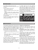
Forming
the
“P”
Trap
CAUTION
The
HRV
is
designed
to
operate
with
ducting.
When
first
starting
the
HRV,
measure
the
amp
draw
to
each
motor
at each speed
to
ensure
it
is
operating
at
or
below
the
max
rating.
Maximum AMP Rating
HIGH
MED.
LOW
1200 POOL
1
9.4
6.0
4.5
700 POOL
4.5
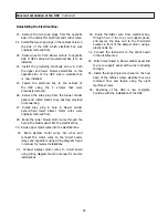
In
order
to
prevent
electric
shock
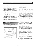
when cleaning or servicing the HRV, it is
extremely important to confirm the polarity
of the power line that is switched by the
safety (disconnect) switch whose control
arm is located on the outside of the
electrical control box area. The hot line
(black) is the proper line to be switched.
To confirm the proper polarity, use a
voltmeter or test lamp to make sure there is no
power after the switch when the door is
open. Check between that point and ground
(on the cabinet). This must be done as
occasionally some buildings are improperly
wired. Always make sure the HRV is properly
grounded.
WARNING
Installation Steps:
1) Insert the drain spout through the hole in the drain pan.
2) Hand tighten the lock nut which holds the drain spout in place.
3) Construct a P-trap using the plastic tee connector.
4) Cut two lengths of 1/2 in drain hose (not included) and connect the other
ends to the two drain spouts.
5) Position the tee connector to point upward and connect the drain line.
6) Tape or fasten base to avoid any kinks.
7) Slowly pour water into the drain pan of the HRV after the drain
connection is complete. This is to ensure that the drain assembly is
functional and also creates a water seal which will prevent odours from
being drawn up the hose and into the fresh air supply of the HRV.
CAUTION
Summary of Contents for 1200 POOL
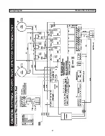
Page 27: ...27 Wiring Diagram Models 700 1200 POOL ...
Page 29: ...29 ...
Page 30: ...30 ...
Page 31: ...31 ...
Page 32: ...info lifebreath com T 1 855 247 4200 F 1 800 494 4185 69 POOL 100516 ...

