2
Introduction
The Recovery Core....................................................3
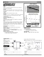
Unit Specifications .................................................4-5
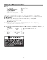
Calculating the Ventilation Rate for the Pool Room.......6
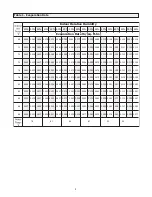
Table 1 - Evaporation Rate.........................................7
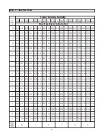
Table 2 - Flow Rate Factor.........................................8
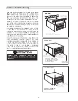
Location of the HRV for Mounting...............................9
The Ductwork System
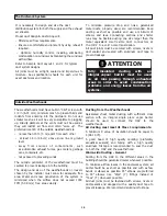
Outside Weatherhoods.............................................10
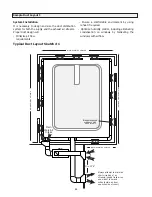
Sample Duct Layout 1..............................................11
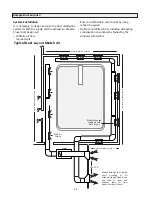
Sample Duct Layout 2..............................................12
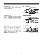
Mode of Operation for the Pool HRV .........................13
Stale Air Return System
Fresh Air Supply System
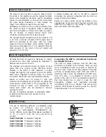
Adjustable Grilles......................................................14
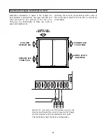
Reversing the Supply and Defrost Air Ports ................15
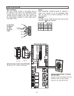
Function and Controls ..............................................16
Drain Connections....................................................
19
Electrical Connections
Balancing the HRV ...................................................2
0
Make Up Heat
Defrost Time Adjustment...........................................2
1
Maintenance and Service .....................................2
2
-2
3
Troubleshooting Your HRV System ............................
2
6
Wiring Diagram................................................
.
........
2
7
Warranty..................................................................
28
Leave this manual with your customer!
Installing Contractor
Telephone / Contact
Serial Number
Installation Date
Model
TO BE COMPLETED BY CONTRACTOR AFTER INSTALLATION
Table
of
Contents
Reverse Installation of the HRV ............................2
4
-
2
5
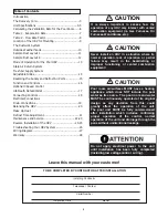
Never install an HRV in a situation where its
normal operation, lack of operation or partial
failure may result in the backdrafting or
improper functioning of vented combustion
equipment!
It is always important to assess how the
operation of any HRV may interact with vented
combustion equipment (ie. Gas Furnaces, Oil
Furnaces, Wood Stoves, etc.).
Do
not
apply
electrical
power
to
the
unit
until
installation
has
been
fully
completed
(including
low
voltage
control
wiring).
CAUTION
CAUTION
Pool room air/surfaces
MUST
have a heating
appliance which does NOT include the pool
water as its source.
The pool room and water
MUST be continuously operated at its original
design as any deviation from this could
greatly effect the operation of the unit.
The pool unit MUST be fully commissioned
after installation which includes confirming
proper operation of the control, normal
operation of the unit and drainage through the
pans without unintentional leakage.
CAUTION
Optional 3 Speed Control
Lifebreath Dehumidistat ...........................................1
7
Connecting Controls ............
.............
...........
.....
........
1
8
Summary of Contents for 1200 POOL
Page 27: ...27 Wiring Diagram Models 700 1200 POOL ...
Page 29: ...29 ...
Page 30: ...30 ...
Page 31: ...31 ...
Page 32: ...info lifebreath com T 1 855 247 4200 F 1 800 494 4185 69 POOL 100516 ...

