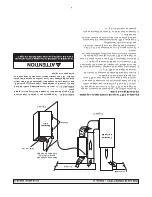
Metal Hanging
Straps (Supplied)
& Mounting Bolts
7" Collar
Foam
Air
Cleaner
Return Air
Forced Air
Furnace
Return Air
Supply Air
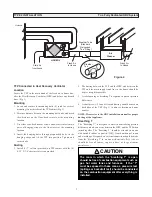
TFP Directly Connected to Forced Air
Heating System
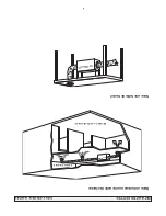
1. Install 7” collar (provided) on top and bottom of TFP
(Fig. 1). Use (4) 8/32” X 3/8” screws (provided).
2. Remove protective backing from pieces of foam and
stick them to the 4 corners of the TFP on the side being
mounted against the plenum.
3. Remove the 4 mounting bolts from the back of the TFP
cabinet. (Fig. 1)
4. Attach top and bottom mounting brackets (provided)
vertical to the TFP cabinet and reinstall mounting bolts.
5. Lift the TFP into position. Edge of TFP must be
positioned on plenum to allow clearance needed for
latches.
6. Install the (4) 8/32” X 3/4” mounting screws (provided)
through the brackets and into position. Tighten and
secure.
7. TFP should now sit securely against the plenum with the
foam in between.
8. Cut 2 - 7" holes in the return air plenum. Install ducting
to join TFP to the return air plenum (Fig. 2).
OTE:
Do not support the weight of the TFP on the
duct. Duct must be open and not pinched.
OTE:
Due to possible noise transfer through the duct
system, it may be preferable in some situations to hang
the TFP a short distance from the plenum, and connect
by running flexible ducting between them. Four nylon
hanging straps are provided for this option.
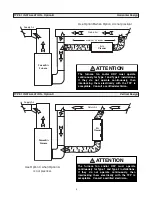
TYPE 1 INSTALLATION - Option A
Standard Design
The furnace fan and/or HRV must operate
continuously for Type 1 and Type 2 installations.
If they do not operate continuously, then
interlocking them electrically with the TFP is
acceptable. Consult a certified electrician.
ATTENTION
Figure 1
Figure 2

