


Page | 6
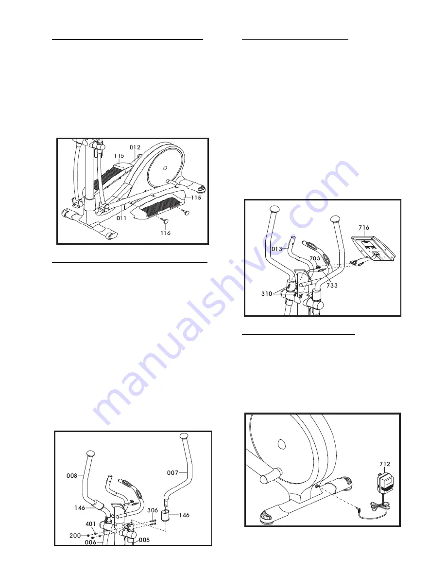
Step 10: Adjustable Foot Pedal Assembly
A. As illustrated below, locate and slide the
adjustable foot pedals (115) onto the left
and right foot pedal tubes (011 & 012).
Locate and tighten foot pedal knobs (116)
to the adjustable foot pedals to firmly
secure them in place.
Note: The adjustable
foot pedals can be adjusted to your
personal preference; however, we suggest
starting with the middle setting number 3.
Step 11: Dual Action Handle Bar Assembly
Tools Needed:
13mm wrench
A. As illustrated below, slide the top pivot
covers (146) to the dual action handles
(007) & (008).
B. Insert the dual action handles (007 & 008)
into the top of dual action arm (005 & 006)
Note: Left and Right stickers on handle
bars
.
C. Locate hardware bags and secure with Qty.
4 bolts (306), Qty. 4 washers (401) and Qty.
4 nuts (200). Using a 13mm wrench, tighten
nuts firm. Slide top pivot covers over
hardware.
Step 12: Computer Assembly
Tools Needed:
Philips screw driver
A. Locate computer console
(716) and
connect computer cable (703) and hand
pulse cable (733) to the computer.
B.
Feed the excess cables back in the
stationary handle bar (013).
Be careful not
to pinch wires.
C. Unscrew Qty. 4 computer screws from the
back of the console, and fix the console to
the top of the stationary handle bar (013).
Using a Philips screw driver, tighten the
Qty. 4 computer screws to console firm.
Step 13: Power Cord Assembly
A. Attach the AC adaptor jacket into the
power socket on the main frame before
plugging the power cord plug into the wall
outlet. Turn the AC power switch on. Flip
the ON/OFF switch to the
ON
position. "0"
sign is for
OFF
; "I" sign is for
ON
.


