9
|
P a g e
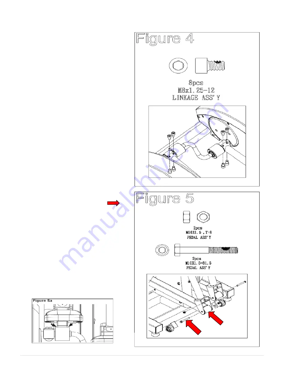
Assembly Figure 4 & 5
FIGURE 4
Note:
The linkage is secured to the
sleeve with three M8*1.25-12 hex
bolts on the top and one M8*1.25-12
hex bolt on the bottom.
¾
Locate bag labeled
Figure 4.
¾
Lift and place left linkage from
handrail assembly onto shaft
sleeve. Align holes together.
¾
(
See Figure 4
) Secure linkage
arm to unit using Qty. four
M8*1.25-12mm Hex bolts.
Tighten Bolts.
¾
Repeat same steps for right side.
FIGURE 5
Note:
It is recommended that two
adults align and secure the pedal tube
assemblies to the handrail
assemblies.
Note:
Use assembly grease on Pivot
Points prior to connection arms.
¾
Locate bag labeled
Figure 5
.
¾
(
See Figure 5
) Locate right pedal
tube assembly. Secure pedal tube
assembly to the handrail assembly
with Qty. one M10*1.5-81.5 hex
bolt and Qty. one M10*1.5 hex
nut. Tighten Bolt and nut snug
(Not Too Tight).
¾
Please ensure that pedal arm is
aligned in the center of roller
wheel while tightening M10*81.5
bolt. Repeat for the left side.
Summary of Contents for LC-CD500
Page 2: ...2 P a g e...
Page 6: ...6 P a g e...
Page 29: ...29 P a g e...


